Dateline - 05/14/2016. Didn't make a lot of headway this weekend. Spent most of the day trying to get the B&M shifter to work correctly. This required crawling under the car, then getting up and moving the shifter, then crawling under the car again, repeat, repeat, repeat, repeat repeat! Yikes!
For the life of me I could not get the shifter to engage correctly. The idea is that it needs to engage correctly at the end of the range (e.g. Park and 1st) with no binding on the linkage. I could not get it to do that. I could get park to work and 1st would be bound. Get 1st to work and Park would be bound. Three hours of under the car, in the cabin, under the car, in the cabin really took a toll. Finally, I stopped and looked at the installation of the cable on the shifter mechanism. Low and behold, I installed the cable on the shifter incorrectly! All I can say is, "RTFM Ed!" After reinstalling the cable correctly, everything worked perfectly! That was a real waste of four hours and a lot of crawling under the car!
To get a little break, I decided to work on the gas caps. I partially installed the right hand gas cap base, but didn't have the correct hardware, so it is in there with a couple of screws. I also bought two complete gas caps from ebay because I needed some parts that had broken on the originals. Both of these are in pretty rough shape but these things are unobtainium so you have to take what you can get. I spend about an hour sandblasting the parts, but now need to find some fuel proof rubber material for the gaskets. Looks like I need to spend some hours on the interwebs!
I do have good news on the rest of the body panels. I called the paint shop and they said they should have the rest of the panels ready to pick up by the end of the week! I'm getting close to being done with the interior so this will be good timing. I'll store the parts in the house until I'm ready to hang them, but that shouldn't be to long!

Monday, May 16, 2016
Thursday, May 12, 2016
Art to Part
Dateline - 05/07/2016 - This weekend I spend doing more mechanical work
under the car. I had a few things hanging, literally under the car that
needed to be taken care of. First was wiring to the electronic
speedometer sensor on the transmission. Another was the Transmission
lockout that is connected to the brake light switch. Basic wiring
stuff, but it takes time to create a nice wire loom and fit connectors.
Still another thing that I needed to do was hook up the B&M shifter cable to the transmission. I had jury rigged this before (http://leapingv8s.blogspot.com/2009/06/steering-wheel-shifter-and-tunes-plus.html) and after I looked at it again, I really wasn't happy with the results since it didn't look like it was completely engaging in Park. So this time I decided to install this the correct way, but need to get a special bracket from B&M for my TH700R4 transmission. So I put that on order and am waiting for the parts.
I also started getting ready to start the car by changing the oil and filter, filling the antifreeze and power steering pump. I even filled the window washer reservoir and bought a new battery. All I need now is fuel. I still have to put the fuel line from the gas tanks to the engine bay back up. I took it down to deal with the crimped fuel line last winter and still need to put it back. I also need to put the fuel tank caps back on. I needed to paint the area around the fillers (I don't know why the paint shop didn't paint them but they didn't), so I used high temp engine paint (black) to finish that off. Now I just need to reinstall the caps.
So, you may be wondering about the name of my post this week. During the week I did some more part creation on my 3D printer. After putting all the dash back together, I realized I needed a knob for the hazard light switch. If you remember, I use a mid-70's GM indicator switch assembly to replace the non-functional Jaguar item. What I liked about that solution is that it has the hazard switch is built into mechanism. This means that I don't have to wire in a different switch. But because of the way I installed the turn indicator, the hazard switch is at the 4:00 o'clock position, which puts it a bit out of the way. I had to glue a piece of brass wire in place to extend the mechanism outside of the steering column cover and once I got everything into place, I realized I needed a knob.
This is where the art comes in. Using Blender (www.blender.org) I designed a knob that I thought would look good and do the job. As you can see from the pictures, I went through many iterations before I got one that looked the way I wanted it to. This is the nice thing about this rapid prototyping capability of 3D printing. Each knob only took about 20 minutes to print, so I could make quick changes, print the knob and try it. Rinse and repeat.
The process is to first create the part in Blender (or any other 3D tool like Sketchup or Maya). There are some things you have to think about when working in the tool. First, for blender, the Z axis needs to be up. Second, you want to make sure that none of the faces obscures a vertex. This is a bit fiddly on a very complex object, but it is critical because the slicing software cannot determine how to create a face if the vertex is hidden. Third, you need to make sure to remove any duplicate vertexes (Mesh > Vertex > Remove Doubles). Forth, you need to make sure the mesh is manifold, meaning, here are no holes. You can check this in edit mode by deselecting everything and then using the Select > Non-manifold option. This will highlight any vertices that do not have a face connecting them. Finally, you need to apply a Triangulate modifier. This modifier will convert all the polygons to triangle which helps the STL conversion. Once all the above prep is done, the file is exported as an .STL file, making sure that all modifiers are applied (Blender has an option to do this during the export).
Once you have the file exported, the next step is to "slice" it. I use an open source software called Slic3r to do this. There are many other tools available and each has strengths and weaknesses. You find this out when you get into the REPRAP world. I like this tool because I know it best and get good results for what I print!
The tool has all the parameters you need to create a driver file that can be used on the printer, things like how thick each layer should be, do you need supporting material so that overhangs do not sag, how much infill you want inside the object, how hot the printer extruder should be, etc. It's pretty complicated and depends on the type of material you are printing. A lot of trial and error (and reading the internet) is needed to get the correct settings, but I think I found a sweet spot.
Once you bring your STL file into the slicer tool, you run the tool to create a GCODE file. The GCODE file is used by the printer driver software to drive the printer. It contains data needed to set the printer (extruder temp, print head speed, etc.) as well as data for each slice of the object. The software will look at the STL file from the bottom and determine how to drive the printer head to print that layer. It then moves up and determines the next layer. It does this until each layer for the object is defined.
Once you have the GCODE file, you are ready to print. Depending upon your printer make, there are various applications to run it. I use Pronterface, which is a common open source print driver application. Pronterface is the direct interface with the printer. It allows you to manually set the temperatures of the extruders, move the print head and print base and several other items. With the GCODE file loaded into the Pronterface application, it's a simple matter of heating everything up and then pressing the Print button.
This sounds like a lot of work, but the biggest amount of time is taken in creating the model in Blender. Slicing takes almost no time if all the prep work is done correctly in Blender and the print takes as long as it takes based on the complexity and size of the model.
Another item I created was the dimmer control knob. As I talked about in a prior post (http://leapingv8s.blogspot.com/2016/04/dash-you-would-think-id-be-done-by-now.html), I had to find a place to put the dimmer control and decided to put it between the steering column and the master power switch. Since this is a very custom solution, I needed to create a custom knob. Using the same steps as above, I created the knob that you see here:
So there you have it!
The really cool thing is that I can send the GCODE file to a custom manufacturer and they can create my objects is other materials like aluminum or steel. The same file is used to drive 4 axis milling machines and other industrial tools, so if I needed something in a more durable material then ABS plastic, all I have to do is find a vendor and send them the file!
Still another thing that I needed to do was hook up the B&M shifter cable to the transmission. I had jury rigged this before (http://leapingv8s.blogspot.com/2009/06/steering-wheel-shifter-and-tunes-plus.html) and after I looked at it again, I really wasn't happy with the results since it didn't look like it was completely engaging in Park. So this time I decided to install this the correct way, but need to get a special bracket from B&M for my TH700R4 transmission. So I put that on order and am waiting for the parts.
I also started getting ready to start the car by changing the oil and filter, filling the antifreeze and power steering pump. I even filled the window washer reservoir and bought a new battery. All I need now is fuel. I still have to put the fuel line from the gas tanks to the engine bay back up. I took it down to deal with the crimped fuel line last winter and still need to put it back. I also need to put the fuel tank caps back on. I needed to paint the area around the fillers (I don't know why the paint shop didn't paint them but they didn't), so I used high temp engine paint (black) to finish that off. Now I just need to reinstall the caps.
So, you may be wondering about the name of my post this week. During the week I did some more part creation on my 3D printer. After putting all the dash back together, I realized I needed a knob for the hazard light switch. If you remember, I use a mid-70's GM indicator switch assembly to replace the non-functional Jaguar item. What I liked about that solution is that it has the hazard switch is built into mechanism. This means that I don't have to wire in a different switch. But because of the way I installed the turn indicator, the hazard switch is at the 4:00 o'clock position, which puts it a bit out of the way. I had to glue a piece of brass wire in place to extend the mechanism outside of the steering column cover and once I got everything into place, I realized I needed a knob.
 |
| Steering column with indicator switch mechanism exposed. Note brass wire at the 4:00 position. This is connected to the hazard switch. |
 |
| Hazard switch wire with steering column cover installed. |
 |
| With newly created (but unpainted) knob. |
This is where the art comes in. Using Blender (www.blender.org) I designed a knob that I thought would look good and do the job. As you can see from the pictures, I went through many iterations before I got one that looked the way I wanted it to. This is the nice thing about this rapid prototyping capability of 3D printing. Each knob only took about 20 minutes to print, so I could make quick changes, print the knob and try it. Rinse and repeat.
 |
| No, there are not monster teeth! They are many attempts at creating the knob. Progression is right to left. |
 |
| Final knob in Blender. |
The tool has all the parameters you need to create a driver file that can be used on the printer, things like how thick each layer should be, do you need supporting material so that overhangs do not sag, how much infill you want inside the object, how hot the printer extruder should be, etc. It's pretty complicated and depends on the type of material you are printing. A lot of trial and error (and reading the internet) is needed to get the correct settings, but I think I found a sweet spot.
 |
| Slic3r Application with knob loaded and ready for export to GCODE. |
Once you have the GCODE file, you are ready to print. Depending upon your printer make, there are various applications to run it. I use Pronterface, which is a common open source print driver application. Pronterface is the direct interface with the printer. It allows you to manually set the temperatures of the extruders, move the print head and print base and several other items. With the GCODE file loaded into the Pronterface application, it's a simple matter of heating everything up and then pressing the Print button.
 |
| Pronterface application used to drive the printer. The knob is loaded and the printer is ready to go. |
 |
| Printer putting down second layer of plastic. The front face of the knob is sitting against the bed. |
 |
| Knob just after print finished. |
Another item I created was the dimmer control knob. As I talked about in a prior post (http://leapingv8s.blogspot.com/2016/04/dash-you-would-think-id-be-done-by-now.html), I had to find a place to put the dimmer control and decided to put it between the steering column and the master power switch. Since this is a very custom solution, I needed to create a custom knob. Using the same steps as above, I created the knob that you see here:
 |
| Dimmer control shaft sticking out of fascia. |
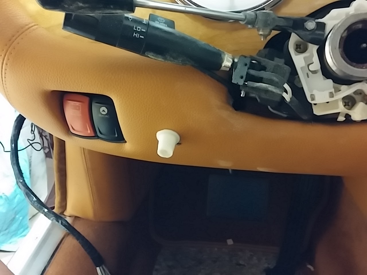 |
| With knob. |
So there you have it!
The really cool thing is that I can send the GCODE file to a custom manufacturer and they can create my objects is other materials like aluminum or steel. The same file is used to drive 4 axis milling machines and other industrial tools, so if I needed something in a more durable material then ABS plastic, all I have to do is find a vendor and send them the file!

Monday, May 2, 2016
Machinical Work
Dateline - 04/30/2016 - I was getting a bit tired of working on the interior so I decided to do some mechanical work this weekend. My main focus was getting the exhaust manifolds sandblasted, coated and installed. This took a lot of time because I could only sandblast for about 10 minutes before I ran out of air and needed to stop to let the air compressor build back up. I don't like to continue sandblasting while the air compressor is running because it takes that much more time to build up pressure and causes the compressor to get really hot. So, I can do about 4" x 4" section, then stop and do something else on the car.
The something else was to put on new rubber brake lines to the front wheels and hook up the brake lines to the master cylinder. I had purchased brake lines several years ago and have been putting off putting them on until I got close to done. This seemed like a good time, so I installed both sides. I also installed the brake pipes to the master cylinder, which wasn't difficult.
I also took the plugs out of the engine, put some oil into the cylinders and turned the engine by hand to make sure the pistons are free. Everything turned easily, so that was a good sign.
So, once I got the exhaust manifolds sandblasted, I treated each one with Calyx manifold coating (http://www.eastwood.com/calyx-manifold-coating.html). This paste is very easy to put on with a toothbrush and really makes the manifolds look good.
Once coated, I installed the manifolds on the engine and connected the exhaust collectors. The passenger side is pretty easy, but the driver side was a real bear because of the steering rack. Needed to have multiple extensions and universal joints to get the inside bolt tight. But patience prevailed and I got everything installed. Here are pictures:
So, I don't have much left to do in the engine bay at this point. Need to put in fluids (antifreeze, power steering, brakes and change the engine oil/filter), and connect the fuel line from the gas tanks that I disconnected.
The something else was to put on new rubber brake lines to the front wheels and hook up the brake lines to the master cylinder. I had purchased brake lines several years ago and have been putting off putting them on until I got close to done. This seemed like a good time, so I installed both sides. I also installed the brake pipes to the master cylinder, which wasn't difficult.
I also took the plugs out of the engine, put some oil into the cylinders and turned the engine by hand to make sure the pistons are free. Everything turned easily, so that was a good sign.
So, once I got the exhaust manifolds sandblasted, I treated each one with Calyx manifold coating (http://www.eastwood.com/calyx-manifold-coating.html). This paste is very easy to put on with a toothbrush and really makes the manifolds look good.
Once coated, I installed the manifolds on the engine and connected the exhaust collectors. The passenger side is pretty easy, but the driver side was a real bear because of the steering rack. Needed to have multiple extensions and universal joints to get the inside bolt tight. But patience prevailed and I got everything installed. Here are pictures:
 |
| Before and after sandblasting |
 |
| Exhausts. Top pre-sandblasting, bottom, sandblasted and treated with Calyx |
 |
| Passenger side with exhaust and plug wires |
 |
| Driver side exhaust with plug wires |
Monday, April 25, 2016
Worked on Another Car This Weekend
Dateline - 04/23 and 04/24 2016 - Occasionally in this blog I go a little off topic and talk about other things going on in my life. This weekend I attempted real motor sport for the first time. I was offered an opportunity to be a driver for a team in a series called Lucky Dog Racing (http://www.racelucky.com/). The cars are only supposed to have originally cost $2,500 and run on street legal tires or you get penalty points. Of course, after getting it race ready, it is significantly more!
The team I raced with was "Team Odin" who is championing a 1980 Rover P3500 SD1 (https://en.wikipedia.org/wiki/Rover_SD1) with the aluminum block 3.5 liter V8. This engine has a long and storied history which you can read if you so desire (https://en.wikipedia.org/wiki/Rover_V8_engine). Team Odin has been racing this car since 2011 and, well it's not as fast as a lot of the other cars out there. It's heavier than a lot of the cars, hasn't had huge amount of suspension or brake modes, and is a bit under powered. Not the kind of car you would think would be a road course car. But it is a race car all the same and a great test bed to learn how to drive competitively. Here are pictures:
Well, the owner Chris was kind enough to invite me along on their team as a driver. I bought all the requisite safety gear (full race suit, helmet, shoes, gloves, etc.) and headed up to The Ridge (http://ridgemotorsportspark.com/) in Shelton Friday night to be ready to race on Saturday morning.
Saturday morning was cold and wet and we were all talking about how the car handles in the wet. Never having driven this car before and never seen the tack, I was a little concerned but confident. A little too confident. But more on that in a minute. The first 40 minutes of the morning was going to be qualifying. They wanted each of the drivers to take the car for three or four laps so they could get an average speed. Chris the owner took the car the first four laps and it was fine although I found out later he did get it a bit loose on one of the corners.
Then it was my turn! I got into the car and proceeded to do a pretty good first lap considering I was all over the course and had cars passing me! But as I started my second lap I lost the back end and slid backward into the curve on turn 1. The car started hard and I finally got it running and started up the climb on turn 2 and 3 and then the engine really started dogging, I made it to turn 8b before it started belching blue smoke and the car died.
After many profane expletives (all caught on the Go-Pro!), I got a tow back to the paddock. We took the hood off and there was oil everywhere. Not a good sign. We could figure out at first why until we discovered the hole in the side of the engine below the #2 cylinder. Yup! I put a rod through the block! I SERIOUSLY BROKE THE CAR!
Now at this point I have to thank the magnanimity of the car owner and the rest of the team! I was devastated! Not only had I broke the car, but I ruined the chances of the team racing on Saturday and possibly the whole weekend! We all spend a lot of money to get into this race, plus time, energy and expectation. NEVER ONCE, and I mean this, did the team ever blame me for the engine! In fact, they were more then generous with me in giving me their experiences with the car and incidents they have had with breakdowns. And the statement, "This is racing" was said to me probably more then 100 times! I still felt (and feel) horrible about taking out the car. But that appears to be my burden to let go of!
So, what to do next. Well, we had an extra engine in the support truck, so it was time to change it out. At least I had a chance to redeem myself by putting all my efforts into this! We proceeded to pull the old engine out, leaving the transmission in the car. Of course, an engine pull is a lot of work and something nice to do in a shop with heat and a lift, not under a tent with rain and wind! But we prevailed and got the old engine out, which made quite a conversation piece, and the new one in. We were buttoned back up and ready to go around 8:00 pm. Just in time have a few beers.
The other thing I have to say about the team is that they are VERY creative! We had a few issues with the engine swap. First, the engine that was in the car was an America version from the 1960's. We were putting back the 1980 Rover version which had a few distinct differences. It has a different oil pump interface so we could not use the Accel electric ignition/distributor from the old one, which means we lost the rev limiter. The old engine used studs for the exhaust manifolds while the Rover used bolts (run to the hardware store!) Also, we forgot to bring the clutch spline alignment tool, which is pretty critical. The good news was that the car now had a Ford T4 transmission, so we went to one of the Mustang teams racing that day and they had the correct alignment tool.
But the real creative solution for the day was the transmission shaft pilot bearing. The one in the old engine was designed to fit the American crankshaft and the T4 transmission. The one in the Rover engine was smaller in both outside and inside diameters. We tried to drill out the bearing, but ended up breaking it. No parts store in Shelton carried a bearing for a 1980 Rover, so we got creative. We went to the local Ace Hardware and found a brass pipe fitting that had the correct inside dimensions with a small smooth area for the race, and larger outside area with threads. We put the fitting into a drill bit wrapped with electrical tape, mounted the drill on a vice and using a flat file, filed the outside down until we were able to hammer it into the crank! That was some real thinking on the fly!
So, what were the results of our labor? We got a full day of racing in on Sunday. We had to come in twice because a rubber water plug broke, twice! Easy fix and no damage to the engine.
Here are some pictures of me racing:
My experience? Racing is really hard! You are trying to learn a track, how a car handles and deal with a bunch of much faster cars passing all the time. To be honest, after 30 minutes I was exhausted and noticed that I was loosing concentration so I came in. I didn't want to break the car again and felt that caution was better suited for the day. I did get a chance to run again one last time and felt much more comfortable even though the car was pretty rough running. I still babied it, and felt good that I made it through the race.
Will I race again? Yes. I don't think I'm a natural race driver, but I want to get some more experience doing this. I think I can like it if I can get past the, "don't break the car" feeling. But even if I don't race again, I'm glad I got the chance to try it at least once!
The team I raced with was "Team Odin" who is championing a 1980 Rover P3500 SD1 (https://en.wikipedia.org/wiki/Rover_SD1) with the aluminum block 3.5 liter V8. This engine has a long and storied history which you can read if you so desire (https://en.wikipedia.org/wiki/Rover_V8_engine). Team Odin has been racing this car since 2011 and, well it's not as fast as a lot of the other cars out there. It's heavier than a lot of the cars, hasn't had huge amount of suspension or brake modes, and is a bit under powered. Not the kind of car you would think would be a road course car. But it is a race car all the same and a great test bed to learn how to drive competitively. Here are pictures:
 |
| Car on Sunday Morning |
 |
| Car on Sunday morning. Owner Chris standing behind |
 |
| Car on Sunday morning |
 |
| Car on Sunday morning |
 |
| The office |
 |
| One of the mascots |
 |
| You gotta have a horned helmet! |
 |
| "Nice Ass!" |
Saturday morning was cold and wet and we were all talking about how the car handles in the wet. Never having driven this car before and never seen the tack, I was a little concerned but confident. A little too confident. But more on that in a minute. The first 40 minutes of the morning was going to be qualifying. They wanted each of the drivers to take the car for three or four laps so they could get an average speed. Chris the owner took the car the first four laps and it was fine although I found out later he did get it a bit loose on one of the corners.
Then it was my turn! I got into the car and proceeded to do a pretty good first lap considering I was all over the course and had cars passing me! But as I started my second lap I lost the back end and slid backward into the curve on turn 1. The car started hard and I finally got it running and started up the climb on turn 2 and 3 and then the engine really started dogging, I made it to turn 8b before it started belching blue smoke and the car died.
After many profane expletives (all caught on the Go-Pro!), I got a tow back to the paddock. We took the hood off and there was oil everywhere. Not a good sign. We could figure out at first why until we discovered the hole in the side of the engine below the #2 cylinder. Yup! I put a rod through the block! I SERIOUSLY BROKE THE CAR!
 |
| Hole in block partially hidden by motor mount |
 |
| Motor mount removed, much better view of hole |
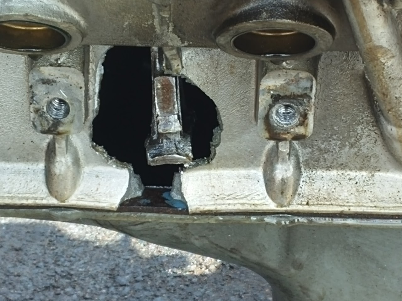 |
| "I don't think that rod is supposed to be there! |
So, what to do next. Well, we had an extra engine in the support truck, so it was time to change it out. At least I had a chance to redeem myself by putting all my efforts into this! We proceeded to pull the old engine out, leaving the transmission in the car. Of course, an engine pull is a lot of work and something nice to do in a shop with heat and a lift, not under a tent with rain and wind! But we prevailed and got the old engine out, which made quite a conversation piece, and the new one in. We were buttoned back up and ready to go around 8:00 pm. Just in time have a few beers.
The other thing I have to say about the team is that they are VERY creative! We had a few issues with the engine swap. First, the engine that was in the car was an America version from the 1960's. We were putting back the 1980 Rover version which had a few distinct differences. It has a different oil pump interface so we could not use the Accel electric ignition/distributor from the old one, which means we lost the rev limiter. The old engine used studs for the exhaust manifolds while the Rover used bolts (run to the hardware store!) Also, we forgot to bring the clutch spline alignment tool, which is pretty critical. The good news was that the car now had a Ford T4 transmission, so we went to one of the Mustang teams racing that day and they had the correct alignment tool.
But the real creative solution for the day was the transmission shaft pilot bearing. The one in the old engine was designed to fit the American crankshaft and the T4 transmission. The one in the Rover engine was smaller in both outside and inside diameters. We tried to drill out the bearing, but ended up breaking it. No parts store in Shelton carried a bearing for a 1980 Rover, so we got creative. We went to the local Ace Hardware and found a brass pipe fitting that had the correct inside dimensions with a small smooth area for the race, and larger outside area with threads. We put the fitting into a drill bit wrapped with electrical tape, mounted the drill on a vice and using a flat file, filed the outside down until we were able to hammer it into the crank! That was some real thinking on the fly!
So, what were the results of our labor? We got a full day of racing in on Sunday. We had to come in twice because a rubber water plug broke, twice! Easy fix and no damage to the engine.
Here are some pictures of me racing:
 |
| Fueling before my time |
 |
| Strapped in and putting in steering wheel |
 |
| Just exiting turn 13 into 14 |
 |
| Heading into 14 |
 |
| Heading into 14 |
 |
| Hitting apex at 14 |
 |
| At apex on 14 |
 |
| Exiting 14 |
My experience? Racing is really hard! You are trying to learn a track, how a car handles and deal with a bunch of much faster cars passing all the time. To be honest, after 30 minutes I was exhausted and noticed that I was loosing concentration so I came in. I didn't want to break the car again and felt that caution was better suited for the day. I did get a chance to run again one last time and felt much more comfortable even though the car was pretty rough running. I still babied it, and felt good that I made it through the race.
Will I race again? Yes. I don't think I'm a natural race driver, but I want to get some more experience doing this. I think I can like it if I can get past the, "don't break the car" feeling. But even if I don't race again, I'm glad I got the chance to try it at least once!
Monday, April 18, 2016
Dash! You Would Think I'd Be Done By Now!
Dateline - 04/16/2016 - Okay, another day working on the dash. This weekend was spend getting the drivers side fascia to fit correctly. This has been a real pain and has required a lot of refitting to make things work. First, I needed to mount the dash dimmer rheostat and control box. I knew I wanted to have this between the switches and steering column, but there is a lot of foam there that holds the dash. So I used a piece of brass tubing to act as an extension and mounted the rheostat using an aluminum bracket. The control box is mounted using double sided foam tape. I'm going to print out a knob on my 3D printer to finish this off.
Next I mounted the right and center dash panels uses 3M industrial strength re lockable fasteners. I was thinking of using Velcro, but I thought I would give this a try first.
Next I worked on fitting the left hand dash. I connected all the wires to the speedo, tach and center control console and tried to get the fascia to fit, but it would not fit well around the ignition lock. I didn't like the fit and know if I left it, it would bother me, so I peeled back the vinyl and did quite a bit of sanding. After everything fit, I glued the vinyl back.
Then I had to figure a way to mount the fascia. I opted for a bolt going through the door jam into the left side of the fascia and a bold going through the center console into the right side. Seems strong enough. I epoxied steel tubing into the fascia and center console to add strength. We will see how long it will go. I may be revisiting this design choice in the future.
I did figure out how I am going to do the hazard light switch. I nice piece of brass rod epoxied into the switch and running out to the lower right of steering wheel cover.
Finally, I put the seats back in the car! Hopefully I will not need to take those buggers out again. They are a pain.
So, as it stands now, I need to finish the center console face so that I can put that it. Once that is done, and I re-upholster the steering wheel cover, everything will be in the car!
 |
| Brass tubing used for dash light rheostat |
 |
| Rheostat and control box mounted on fascia |
Next I worked on fitting the left hand dash. I connected all the wires to the speedo, tach and center control console and tried to get the fascia to fit, but it would not fit well around the ignition lock. I didn't like the fit and know if I left it, it would bother me, so I peeled back the vinyl and did quite a bit of sanding. After everything fit, I glued the vinyl back.
Then I had to figure a way to mount the fascia. I opted for a bolt going through the door jam into the left side of the fascia and a bold going through the center console into the right side. Seems strong enough. I epoxied steel tubing into the fascia and center console to add strength. We will see how long it will go. I may be revisiting this design choice in the future.
I did figure out how I am going to do the hazard light switch. I nice piece of brass rod epoxied into the switch and running out to the lower right of steering wheel cover.
Finally, I put the seats back in the car! Hopefully I will not need to take those buggers out again. They are a pain.
So, as it stands now, I need to finish the center console face so that I can put that it. Once that is done, and I re-upholster the steering wheel cover, everything will be in the car!
Monday, April 11, 2016
Still Working On The Dash!
Dateline - 04/10/2016 - Continued to work on the dash this weekend. I've pretty much buttoned up the wiring and cleaned up the loose ends. Almost everything is ready to go except the dash light dimmer control and the hazard warning light switch. I know what I'm going to do with the dimmer control. I'm going to mount it between the two switches and the steering column on the driver's side fascia. I need to get some tubing from the hardware store to do that.
What I don't know is the hazard switch, which is part of the turn signal controls. I'm going to need to do some head scratching to get that to work, but I will!
I also spent some time with the steering column cover (here is a link to when I create it http://leapingv8s.blogspot.com/2012/03/three-months-and-moving-right-along.html). It's a bit too big and the steering column tightening knob rubs against it. So I had to peel off the vinyl and sand it down quite a bit. That's okay though since had some aesthetic issues with that anyway and will make a better one this time.
Finally, I mounted the right had dash. It has bolts that go into brackets I made in the back and then pushes up into position. It is held in place with a five inch piece of steel tubing that is pushed through the center console side into the front of the fascia. You can't see it, but it feel very solid and I think this will hold well. I also mounted the bottom glove box door.
I had to cut my work effort a bit short on Saturday because I needed to wash and was the XK-8. First wax of the season and it needed it. The paint was feeling really dry. It can use a couple more coats to bring back the silky feel that I like.
I also washed the Van, which needed it badly! That was a full day by the time I was done.
What I don't know is the hazard switch, which is part of the turn signal controls. I'm going to need to do some head scratching to get that to work, but I will!
I also spent some time with the steering column cover (here is a link to when I create it http://leapingv8s.blogspot.com/2012/03/three-months-and-moving-right-along.html). It's a bit too big and the steering column tightening knob rubs against it. So I had to peel off the vinyl and sand it down quite a bit. That's okay though since had some aesthetic issues with that anyway and will make a better one this time.
Finally, I mounted the right had dash. It has bolts that go into brackets I made in the back and then pushes up into position. It is held in place with a five inch piece of steel tubing that is pushed through the center console side into the front of the fascia. You can't see it, but it feel very solid and I think this will hold well. I also mounted the bottom glove box door.
I had to cut my work effort a bit short on Saturday because I needed to wash and was the XK-8. First wax of the season and it needed it. The paint was feeling really dry. It can use a couple more coats to bring back the silky feel that I like.
I also washed the Van, which needed it badly! That was a full day by the time I was done.
Monday, April 4, 2016
Still Working on Dash
Dateline - 04/02/2016 - Was only able to work on the car for half a day on Saturday because I had a bunch of yard work that needed to get done. I get the connectors I had ordered from Amazon and was able to wire the center gauge cluster, although it is not installed yet. I also worked on the wiring for the Tach and Speedo and cleaned up a little of the wiring behind the driver side dash. Still have more to do, but pretty close to getting all that bundled up.
I still have a bit more work to do on the center indicator panel. I need to print out the warning light symbols on decal paper and them on some clear plastic. I also have to paint the blue plastic to silver. Lots of odds and ends stuff to take care of. It all takes time!
Once I get the dash installed, I can work on the center console. I still need to finish the carbon fiber panel. After that, it should be matter of installing everything. most everything is already made up connection wise in the center console, so that may go much quicker.
I may go ahead and put the seats back in the car before I do the center console. It's a bit of a pain to sit in the car without seats!
I still have a bit more work to do on the center indicator panel. I need to print out the warning light symbols on decal paper and them on some clear plastic. I also have to paint the blue plastic to silver. Lots of odds and ends stuff to take care of. It all takes time!
Once I get the dash installed, I can work on the center console. I still need to finish the carbon fiber panel. After that, it should be matter of installing everything. most everything is already made up connection wise in the center console, so that may go much quicker.
I may go ahead and put the seats back in the car before I do the center console. It's a bit of a pain to sit in the car without seats!
Subscribe to:
Posts (Atom)