Dateline - 26 January, 2013 - I've been fighting a cold all week and
didn't want to work out in the cold garage, so I did some work on the
electronics I could do in the house. Last week I ordered a 14 Amp, 12 volt DC power supply to test out my wiring. Several weeks ago I bought a
breadboard, jumpers, LEDs, ribbon cable and micro switches for the for
the dashboard indicator console. So I decided to wire up the LEDs and
switches on the breadboard to see if they would work. Here is what I
come up with:
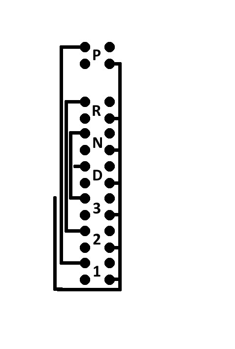
Since I got that working, I then drew up the wiring schematics. I have a
12"x12" PCB board that I am going to use etch the wiring diagram
onto. I found a great source for instruction on doing this here (
http://electrons.psychogenic.com/modules/arms/art/10/PrintedCircuitBoardPCBHOWTOAnIllustratedGuide.php). I
wasn't able to finish to drawings because I need the male 10 pin plugs
that will be soldered to the board, but they are pretty close. Here are
the two drawings.
 |
| Center Light Cluster including Gear Selected, Turn Signals, etc. |
 |
| Circuit board that carries switches mounted in gear selection quadrant. |
Finally, I hooked up the power supply to my rack of eight switches to
see what the LED's look like when they are lit. I have a choice of
either having the lights on all the time, on when the switch is on or
on when the switch is off. They are very bright, so I may want to put
some resistance, or wire two or three in series to reduce the brightness. Here
is what they look light fully lit:
So, once I get the male 10 pin plugs in, I can finish up the wiring
diagrams and start the etching process. I also thought about using my
3D printer to print the diagram on the board if the laser printer option
describe above doesn't work.