Dateline - February 9-10, 2013 - This was a very productive weekend on the car. I had an event planned for the afternoon on Saturday (Chinese Lunar New Year at the Seattle International District), so I knew that I only had a limited amount of time to work on the car, so I decided to figure out where to put the blower fans' speed control resisters.
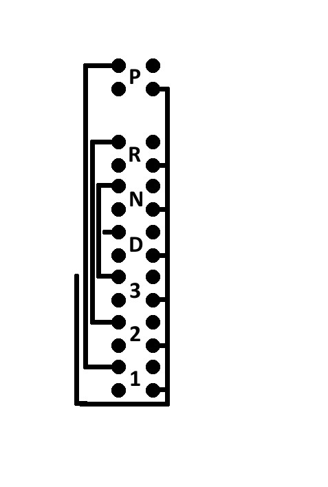
I have a couple of problems caused by my remodel. The fan speed switch that I'm putting in the car has four positions, Low, Medium 1, Medium 2 and High, while the stock car only has three speeds. Also, the car has two fans, one on each side (I'm sure they did that so that the car would be balanced :) while the blower control I'm putting in the car was only designed for one fan. I wasn't comfortable putting twice the current through that switch.
The speed of each fan is controlled through speed control resisters, located in the engine compartment. Each fan has its own set of resistors. When the fan switch is put to low, the current flows through the low and medium speed resisters in series. When the switch is turned to medium, the current flows only through the medium speed resister. When set to high no resisters are used.
So, I could have used the original resisters and just left one of the fan speeds (probably Medium 1) the same as the Low speed, but the prior owner told me he had problems with the fans running all the time, even after the key was turned off. I suspected a short someplace, and the control resisters would be the prime suspect. So I opted to buy two of the speed resisters that are used in the Chevy Astro that I sourced the control switch from. The challenge there is that the resisters need to sit in the airflow of the fan because they get pretty hot! This means that I had to figure out where I could mount the resisters.
First I wanted to see if the fans actually worked with the new resisters. I pulled out the driver side fan (easily accessible from the engine bay) and using my new power supply I was able to try out each setting and sure enough, the fan worked as advertised!
Then I started looking at places to mount the resister pack and noticed that there are two holes in the air box that were originally used for the A/C plumbing. These holes were perfect! Each are in the airflow upstream of the fan, so they will get the cold air coming from outside, plus the holes are on the inside of the car, so I don't need to cut into the firewall! When I had the air box out last year, I covered the holes with aluminum ducking tape. All I had to do was remove the tape, cut the fiberglass so the holes are the right size and screw the resisters down! A happy accident! Believe me, one of the few thus far!
So, since I had a good idea how I was going to solve the problem, and since I was working in the engine bay anyway, I decided to spend the rest of the day stripping the firewall and fenders for painting. I took out the right side fan (and tested it), removed the fan control resisters, the master power solenoid, the heater water control valve, front and back brake lines, +12 volt cables, ground cables, horn, horn relay, ballast resister, Lucas control module and all the little clips, Adel clamps and screws still stuck to the car. Now all I need to do is scrape the rust, vacuum, clean away 42 years of grease/oil and dirt, prime with rust encapsulator and paint!
On Sunday, I sat down and figured out the wiring for the fans. Like I said above, with two fans twice the current load would need to go through a switch only meant for one fan. I was not happy with that, so I decided to run each speed through a solenoid to isolate the current. I would only need three solenoids because the heater control resister unit already had one installed for high speed. It was a pretty easy process of adding three more solenoids to the nice relay frame I built a couple of weeks back. All I really needed to do was the wiring harness. I put together the six wires that needed to run to each of the control units, wrapped them nicely in electrical tape, and installed it into the car. Nice and clean! It took a lot of time but nothing technically hallenging.
I was also able to use the original wiring to run the fans. I was able to use the plug that originally went to the center console for the +12 hot from the fuse box, and since there are two separate power wires running through the firewall, Green/Yellow and Green/Gray, I was able to run the hot from the fan resister on the left side to Green/Yellow and the right side to Green/Gray. So I didn't even need to run new wires to the fans!
Finally, I took my power supply and an ohm meter and tested all the relays. Everything works great.
I still have to screw in the fan resisters and finish the right side resister wiring and the wiring to the control unit (I ran out of female pins), but basically, my fans are done.
This is a big load off my mind because it was one of the last things I was really worried about in this installation. Everything else is pretty much just an easy retrofit. Knock on wood!
Next week, wiring the cruse control.

Monday, February 11, 2013
Wednesday, February 6, 2013
A Bit Distracted This Weekend
Dateline - 02/02/2013 - Didn't do much on the car this weekend. Spent most of the day Saturday driving to and from Portland to look at purchasing a new bike frame from Renovo (http://www.renovobikes.com/). Last month my FELT Z5 carbon fiber frame bike fell over and hit my roller stand and broke the drive side chain stay! Yup! Just falling over and hitting something broke it. Worst of all, FELT's replacement policy is 1/2 off the retail price for a new frame. So I would end up spending about 2/3 the price that I send on the bike NEW just replace the frame. I can't see the value in just about buying another bike to get the same bike again!
So, I've been looking at Renovo for a couple of years now and have thought that a wooden bike frame would be something really unique. I saw one last year while I was riding home on my daily commute and the owner said that it was a really nice ride. So I went down to Portland and tried one out. They are surprising light and very supple. Really no vibration at all is transmitted through the frame. Wood just absorbs all the bumps. Also, wood doesn't break or fatigue like metal or have hidden cracks like carbon. I realized I really don't need an ultralight bike frame. I don't race! Having something I can live with for a long time and is extremely unique is what I'm really looking for! Each frame is made by hand, of specifically choosen hardwords and has ~40 hours of hand work to finish them. They truely are a work of art! So now I'm in the build queue. I still have to choose which woods I want, but I will soon own one of these masterpieces.
Now, back to my other unique ride! Last week I discovered that 3M creates a carbon fiber like vinyl called DI-NOC (http://www.carbonfiberfilm.com/). It's designed to be applied as an architectural element and can last up to 5 years in the sun and can even be clearcoated. I've been really worrying about how I would lay up the center console to get the carbon fiber to go into all the nooks and crannies, as well as all the work necessary to get a glass like finish. Well, this may be the answer. I ordered a test piece and made a fiberglass buck with similar bends and curves as the center console to try it out. I hope it works because it will really make it much easier to get the console done.
Also, I start work on the driver side armrest pad. This is one of the last interior elements that I have to fiberglass and upholster. So, some work done, but I really need to start concentrating if I'm going to get this done by June!
Monday, January 28, 2013
Not Feeling Well, But Work Goes On!
Dateline - 26 January, 2013 - I've been fighting a cold all week and
didn't want to work out in the cold garage, so I did some work on the
electronics I could do in the house. Last week I ordered a 14 Amp, 12 volt DC power supply to test out my wiring. Several weeks ago I bought a
breadboard, jumpers, LEDs, ribbon cable and micro switches for the for
the dashboard indicator console. So I decided to wire up the LEDs and
switches on the breadboard to see if they would work. Here is what I
come up with:

Since I got that working, I then drew up the wiring schematics. I have a 12"x12" PCB board that I am going to use etch the wiring diagram onto. I found a great source for instruction on doing this here (http://electrons.psychogenic.com/modules/arms/art/10/PrintedCircuitBoardPCBHOWTOAnIllustratedGuide.php). I wasn't able to finish to drawings because I need the male 10 pin plugs that will be soldered to the board, but they are pretty close. Here are the two drawings.
Finally, I hooked up the power supply to my rack of eight switches to
see what the LED's look like when they are lit. I have a choice of
either having the lights on all the time, on when the switch is on or
on when the switch is off. They are very bright, so I may want to put
some resistance, or wire two or three in series to reduce the brightness. Here
is what they look light fully lit:

So, once I get the male 10 pin plugs in, I can finish up the wiring diagrams and start the etching process. I also thought about using my 3D printer to print the diagram on the board if the laser printer option describe above doesn't work.

Since I got that working, I then drew up the wiring schematics. I have a 12"x12" PCB board that I am going to use etch the wiring diagram onto. I found a great source for instruction on doing this here (http://electrons.psychogenic.com/modules/arms/art/10/PrintedCircuitBoardPCBHOWTOAnIllustratedGuide.php). I wasn't able to finish to drawings because I need the male 10 pin plugs that will be soldered to the board, but they are pretty close. Here are the two drawings.
 |
| Center Light Cluster including Gear Selected, Turn Signals, etc. |
 |
| Circuit board that carries switches mounted in gear selection quadrant. |

So, once I get the male 10 pin plugs in, I can finish up the wiring diagrams and start the etching process. I also thought about using my 3D printer to print the diagram on the board if the laser printer option describe above doesn't work.
Monday, January 21, 2013
More Electrical work - Auto Headlights
Dateline - January 19, 2013 - Worked on more electrical wiring this weekend. The goal, install the automatic headlight system. I purchased an aftermarket Automatic Headlight with daytime running light system last year. The kit includes a main CPU, a photosensitive diode, an override switch, a set of relays for Headlights and Sidemarkers, and wiring to connect it all together. The Unit has a lot of features including:
- Automatic headlight/sidemarker
- Daytime running lights (headlights only during the day)
- Automatic lights on with windshild wiper turn on (required in some states)
- Interconnection with security system
Since I'm not installing a security system, and didn't want the headlights to come on with the wipers, I removed those wires from the wiring harness.
Next, I determined where I wanted to mount the unit. I'm trying to put all my electrical items in the cavity in the center console, so I found a good place to mount the unit, on the bracket used originally for the Air Flow control levers (left and right).
My next decision was were to put the relays. Well, this car is going to have a lot of relays! I already have a relays for the ignition cutoff switch, and one for the transmission torque lock, and now I have two more for the automatic headlights. As I thought about the new wiring, looked at schematic, and the original wiring, I realized that the original had all the headlight power coming from the battery, into the headlight/sidemarker switches then to the fuse box and to the lights. This means that the two switches have to carry all the current used by the headlights and sidemakers! That's a lot of amps! Even thought the new Aircraft switches could probably take this sort of power, I didn't want to push that kind of current through the switch. This means two more relays. I will also want some relays for interior lights and auxillary power. That makes a total of eight relays.
So, I decided to create a relay frame that I could mount on the transmission tunnel access panel. This required some more sheet metal fabrication including cutting, bending, filing, welding captive bolts onto the frame and the access panel, and painting. But now I have a great place to put all eight relays, and can even put two to four more there if I want.


The last trick of the day was doing the wiring, which required some spelunking around the old wiring harness. I had to find where the hot came into the light switches and then were the headlights and sidemarkers came out. Turns out the Hot and Headlights are in one plug, while the sidemarkers are in another, both on the left hand side of the car. Since I don't want to cut the plugs from the original center instrument cluster (would really impact resale value), I'm creating my own wrirng by building pins that will plug into the existing harness plugs. Once I have all the wires set, then I will build a plug around them using Silicon or RTV.
I still have a little wiring to do. I have to wire the automatic headlight cutoff switch and the actual headlight and sidemarker switches.
I'm pretty happy with how this worked out. Next I'm either going to tackle the heater fan wiring or the cruse control system.
Monday, January 14, 2013
Starting Work - One Item at a Time
Dateline - Jan 12-13 2013 - Have started working on the car again. I've got a lot to do and I noticed that by spring of last year, I was getting very distracted by trying to do too many things at once. So for a while I want to work on only one thing and get it as done as possible. So, this weekend I decided to work on the heater control. Several weeks ago I found a wiring diagram online for the Chevy Astro Van, which is where my heater control and vent door actuator comes from, and spent an evening figuring out the pin configurations. I even jury rigged some wiring and tested that everything worked. I also ordered a Mr. Gasket choke cable, that I am using to drive the heater core water flow valve (from a 70's Ford Bronco) via the actuator motor. The valve needs to be in the engine compartment, while the actuator motor needed to be inside the car. Looking around I found a good spot on the right hand fender well to put the value and a place under the glove box, behind the new fuse holders for the actuator motor. Now I needed to manufacture the components. I'd need a bracket to mount the valve on the firewall, a bracket to mount the actuator, a bracket that mounts to the actuator and holds the cable in place and an arm for the actuator. All of these were cut, filed and drilled out of sheet metal, fitted and painted black. I used stainless steel hardware and nyloc nuts to make sure everything stays were it's supposed to be. I may need to build a small heat shield inside the engine bay depending upon the heat buildup, but I can deal with that as necessary. Here are pictures of the components and installation, including pictures of the valve in closed and open position, driven by the actuator motor.


Saturday, December 1, 2012
Summer Is Gone, Time to get back into the Garage!
Dateline - December 2012 - Well I took a long break from the car to enjoy our spring and summer weather buy biking, some yard work, painting my deck and laying in the hammock. Now it's time to get back to the Jag!
It looks like March was my last update and I got quite a bit done before I stopped for the summer. In fact, I think it would be best to just line out what is done, what is in work, and what is left to do.
Done:
1) All the body filler work is done and 1/2 of the car (passenger side) has been sanded and ready for primer, including doors and door jambs. I still need to do the driver's side.
2) Reconfigured Heating/cooling system
3) Heater core refurbished
4) Headliner and all trim pieces.
5) Dash pad has been upholstered
6) A-Pillar covers upholstered
7) Center Console built and upholstered
8) Passenger side door panel
9) Driver and Passenger side door pockets
10) Upholstery for lower parts of B-pillars
11) Driver side lower dash fascia built and upholstered
12) Steering column cover molded and upholstered
13) Steering column turn signal and cruse control/wiper switch re-work
14) Moved fuse blocks from center of dash to behind lower passenger glove box and replace fuse types from old style glass to modern bayonet type.
15) Wiring to move power window switches to door panels - this was a lot of work!
16) Installation and wiring of a battery cutoff switch
17) Installation and wiring of new oil pressure sensor for new gauge
18) Installation and wiring of new water temperature sensor for new gauge
19) Wired Delphi connectors for headlights and front turn signals and side markers
20) Installation and wiring of transmission torque converter lockup
Started:
1) Carbon fiber center console layup - negative mold has been formed.
2) Carbon fiber window switch bezels
3) Driver's side door panel - was done but needed to rework because the door would not close around the dashboard - As Homer Simpson would say, "Do'h!"
4) Driver's and Passenger door arms - close but need some tweaking to get finished look
5) Passenger side lower dash fascia - Need to finish up the glove box.
6) Wood dash - pieces have been cut but finish work is still required
7) Wiring for Speedo - Need to get adapter for transmission to mate with the sender unit
8) Wiring for Tach
9) Wiring for Instrument lights
10) Wiring of ignition cutout switch
11) Sanding, rust inhibiting and priming passenger side lower rear fender
12) Stripping, cleaning and painting trunk hinges
Not Started:
1) Upper B-Piller upholstery
2) Installation and wiring of cruse control system
3) Installation and wiring of automatic headlight system
4) Installation and wiring of center console switches
5) Installation and wiring of radio
6) Installation and wiring of heater control unit including heat valve control
7) Wiring for NOS system in trunk
8) Wiring AUX power to the trunk
9) Wiring of turn signals
10) Installation and wiring of interior foot well lights
11) Sanding, rust inhibiting and priming driver side lower rear fender
12) Sanding, rust inhibiting and priming front lower fascia (below front bumper)
13) Sanding, repairing and painting interior air circulation tray (unit under back deck)
14) Sending chrome pieces in for re-chroming
15) Fill prime and sand the body
16) Sealing and installation of driver side fuel tank
17) Installation of new passenger side fuel tank
18) Cleaning and installation of evaperative control tubing in truck and C-Pillars
19) Re-installing Brake Peddle, Brake Booster and new Master Cylinder
20) Re-installing Steering Column
21) Re-installing Gear Selection Lever
22) Installation of new Emergency Brake level and cable
23) Installation of sound proofing
24) Final Paint
25) Final re-assembly
The good news is that I believe I have almost all the parts I need. Sitting on my shelf right now are:
1) All new gauges
2) All new switch gear
3) Cruse Control Kit
4) Auto Headlight Kit
5) Components to fabricate hot water control unit for heating system
6) New front and rear window seals
7) New side window rubber seals
8) New side window runner seals
9) New door handle, door lock and trunk lock seals
10) New door seals for all four doors
11) New trunk seal
12) New front turn signal, side maker and rear tail light seals
13) New passenger side fuel tank
14) Fuel tank sealing kit for driver side tank
15) New brake master cylinder
16) Sound proofing
17) Carpet Kit
Need to purchase:
1) Radio
2) Transmission adapter for speedo sender
3) I'm sure some odds and ends I've not thought of yet!
There is still a lot of work to do, but I'm pressing for June 2013 to be done. I think I can do it! Keep watching!
Sunday, March 18, 2012
Three Months and Moving Right Along
Dateline - March 18, 2012 - I just realized that it has been three months since I've posted anything! The car is moving along real well. Thus far I've worked on:
- Left and right front door panels. Pretty much done although I still have a little more upholstery work to do.

- Filled the cracks in the plastic dash pad and covered it in wine colored vinyl.


- Maple dash is cut. Not finished yet, but good enough to work on other components. (no pictures)
- Lower fascia on passenger side has been laid up in fiberglass, covered with vinyl and the glove box is being constructed.


- Created brackets to hold up new passenger fascia.

- Lower fascia on driver side has been laid up in fiberglass and covered in vinyl. Still needs a little more work but it is coming along nicely.


- Repaired, cleaned and painted the steering column. I bought a second hand column last year because the bearings in the original were shot. The second hand column had good bearings but it looks like it had been crushed a bit (in an accident), so I swapped everything over to the old column and cleaned it up. (no pictures)
- Rearranged the turn signal switch because once I got the wood dash in place, I realized that it would not fit. Needed to make the cruse control/wiper control arm into a fixed stalk behind and slightly lower then the turn signal indicator. I used the original turn signal arm and grafted it to the GM turn signal switch gear.


- Molded the steering column cover in modeling clay ("plasticine") and laid fiberglass over that, then vinyl


- Ordered and received new bayonet type fuse blocks that will replace the glass fuses currently in the car. The fuses will be moved from behind the center dash to behind the passenger lower glove-box. This will work great because there is a lot of space there and I have fashioned the glove-box to open all the way so that you can reach in to get to the fuses! I also have four more fuses then I had before, so I can get rid of the inline fuses that were being used for other things like the rear window defroster, radio, transmission lockout, etc.

- Ordered and received Delphi type water resistant connectors for things like the outside turn signals, side markers, etc. I installed some.

- Started a small amount of rewiring of the fuses but have not done much until I'm finished with the inside.


- Ordered the right fuel tank (the one that is Swiss cheese). Still waiting for that to come in. (no pictures)
- Ordered a carpet kit from a company called Lakewell in Belgium (http://www.lakewell.com/en/products/jaguar/xj/full-carpet-set-jaguar-xj6-xj12-s1-saloon-68-73). Should be delivered in a couple of weeks. (no pictures)
So, things are moving along nicely. I have a few more weeks of interior work to do, then I can start concentrating on the wiring, which is going to be a significant effort, but is the last work to do before I go back to bodywork.
Subscribe to:
Posts (Atom)