Monday, December 28, 2015

Christmas 2015

Dateline - 12/24 and 12/26 2015 - I had two solid days on the car over Christmas break and got a lot done, although it really doesn't look like it from pictures.

Thursday 12/24/2015:
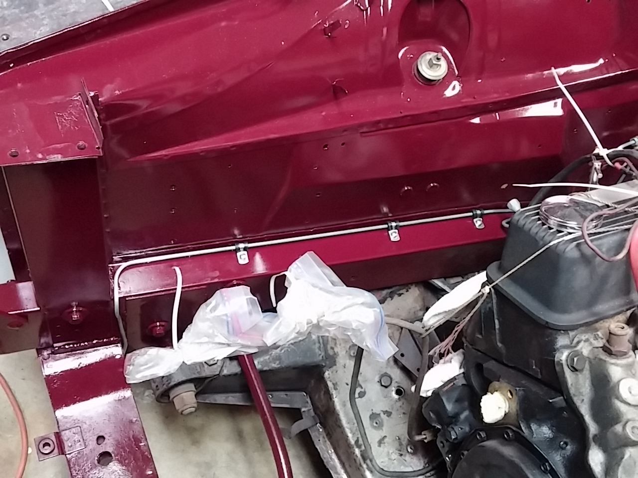
First thing I wanted to do was re-route the fuel line to the carb.  I didn't like it being so close the the heater hoses, so I moved it around to the other side.  Next I put the hose clamps on the heater hoses.  I purchased hose clamps that have chrome anodized aluminum fitting that make them look like pressure fittings.  It's a bit of bling that looks so much better then plain old hose clamps.  I also put on the new distributor cap, which required removing the HEI coil and plug wires from the old one and installing them into the new.  Simple swap but I like the looks much more than the black cap that was on there.

That was all the easy stuff! Next I decided to tackle the wiring.  I've been holding off on this because I knew it was going to be a bear and I wasn't disappointed!  All the original wiring was left in the car after the engine swap out.  A wiring harness that came with the engine swap kit interfaces between the old and the new.  I wanted to get rid of the old wiring that wasn't needed, so I had to figure out how it worked as installed.  It took me several hours of tracing wire, looking at schematics and puzzling over what I had in front of me to figure it all out.

The first puzzle was the starter relay.  This had all the original connections, but some had been removed by someone (me) who did not mark the wires (DUMB!) so I wasn't sure how things needed to go back together.  I had to split apart the wiring harnesses and pull apart connections in the car to trace where all the wires went.  The key was finding the wire that goes from the ignition switch START to the relay.  Because of my extensive re-wire and the the wire color code changing between the engine bay and the inside of the car (Jaguar!) this was no easy feat.  I ended up spending about 1.5 hours with an ohm meeting probing at wires until I figured it out.

Next I had the find the Starter Isolation switch wire which breaks the ground side of the starter relay.  This switch is mounted on the gear shift and is only activated when the car is in Park or Neutral.  This way you can't start the car while in gear.  20 minutes with an ohm meter and I found the wire.  So, now I had everything I needed to hook up the relay.

But of course, I couldn't put a nasty old corroded relay back into the car.  So I spend some time with some metal polish and shined it up to a nice bright gloss!  Then I mounted the relay next to the battery cutout relay, plugged in the wires and voila!

My next challenge was the wiring harness going to the engine.  This thing was nightmare.  This is a harness that come with the engine swap kit so it has a plug that plugs into the existing wiring harness, which is good, but it also has a bunch of extra wires for different Jaguar installations and I had to figure out which were originally used.  I basically needed three wires: 1) A hot wire going from the ignition to the distributor "BAT" terminal, 2) A wire for the oil pressure sender and 3) a hot wire to the automatic choke on there carb.   Once I figured out those wires, I was able remove the unneeded wires, which reduced the complexity quite a bit.

From the alternator, I have the hot wire that goes to the battery, which doesn't use the existing wiring in the car.  Instead a large lead runs from the alternator, across the top of the engine and out the back to the right side hot connection terminal on the firewall.

The alternator also has a plug that has two wires.  One is a hot that energizes the alternator the other is a wire that goes to the "ignition warning light" on the dash.  The hot was easy (just used what was there before) but the ignition warning lamp had me scratching my head because I could not see this ever being hooked up.  It had a bullet connector and there was no wiring in the car where this would fit.  So I'm thinking it was never hooked up.  So I covered the bullet connector and buried the wire back into the harness. I figured if I need it, it will be there and I can easily pull it back out.

While working on this harness, I had a nagging question running in the back of my mind.  "What about the tachometer?"  My experience with cars has been that the tach usually uses a wire that connects to the coil to sense how often the coil is firing.  Well, the HEI unit has a "TACH" plug, but the existing wiring harness has no wire connected to that.  This meant that the tach was getting a signal from someplace else.

Now the real head scratching began.  How did the tach work?  I had to figure this out because I have an aftermarket tack to put in and need to make sure it gets wired in correctly.  When I look at the wires and trace things down, I have a wire running from the tach to one side of the ballast resistor.  On the other side of the resistor I have two wires ganged together, one that runs to the HEI unit and other that goes to the starter relay which I had disconnected as not needed (see above).  How did all of this work? Finally it occurs to me.  Instead of running a hot from the ignition to the ballast relay, to the coil, and another wire from the coil to the tach, Jaguar ran the hot from the ignition through the tack, through the ballast relay, to the coil. This reduced the amount of wire needed.  Of course, if you ever remove the tach, the engine wouldn't run, but who would ever do that?

But what about the hot lead coming from the starter relay going to the coil side of the ballast resistor?  To answer that, we need to review the principles of coil based ignition systems (believe me, I had to look all this up!).  The average coil only needs about 9 volts to operate effectively.  If you run a coil at a constant 12 volts, you will overheat the coil and cause premature failure.  So, to get the maximum life from the coil, you need to step down the voltage.  The easy way to do this is a resister placed in series.  Thus, the ballast resister was born.

But why put 9 volt coils in to begin with?  Why not make then 12 volts?  Hearken back to the days of yor when cars had very low tech carburetors, suspect fuel quality and low compression engines.  Remember, you need three things to get an engine to run, fuel, compression and spark.  In the above scenario, two of the three things you need are poor (fuel and compression).  So what can you do to help the engine start?  Have a very hot spark.  And how would you do that?  Over-energize the coil!  So, in many cars, there is a bypass wire that goes from the starter relay to the coil that will put 12 volts to the coil when the engine is being started to get a hotter spark.  As soon as the car starts, the coil voltage dropped back to 9 volts and everyone is happy. Pretty ingenious actually!  Now this is all fine and good when you have a coil.  HEI systems don't need the power reduction so I could get rid of the ballast resister.  That left me with a spare wire running from the starter relay to the now missing ballast resister.  I'll get back to this wire in a moment.

But I still have a problem.  My tach needs a separate power and tach signal to work.  So, I took the original wire that went from the tack to the HEI unit, cut it and connected it to an unused wire in the new wiring harness and plugged that into the TACH pin of the HEI unit.  I then spliced the HEI BAT wire into the now unused wire that went starter relay/ballast resister which will go to ignition hot (yet to be determined).  So, this should give me hot when the ignition is on, a tach signal and removed the ballast resister.  What a pain, but boy did I feel good once I got this figured out!

My next challenge was mounting the horn relay.  Not too bad.  Of course, I had to polish it too so that it had the right look!

That was enough for one day!

Saturday, 12/26/2015:
More wiring!  I decided to focus on the bunch of wires I have on the left had side of the car.  Here I have:

  • Transmission torque converter lock relay signal
  • Speedometer sensor power and signal
  • Cruse control magnet pickup wires
  • Oil pressure sender
  • Water temperature sender


Everything but the water temperature sender needs to be bundled and run across the top of the firewall, then down into the transmission tunnel.  The oil pressure sender wire comes out of the bundle part way down to run across the gap between the firewall and engine.  This was all pretty straight forward.  I may not need the Cruse control magnet pickup wires if I can successfully get the signal from the tachometer.  I still ran the wires, just in case.  If I don't need them, I'll strap everything up under the car.

I also had a wire to run to the water temperature sender which needed to be wrapped up with the wires going to the cruse control.  I had already wrapped those wires, so I needed to unwrap and re-wrap them.  I hate doing things twice (or three or four times) but it needs to be right.

I next spent some time installing the cruse control linkage.  Since I already have a lot of linkage for the throttle and transmission kick-down, it was a pretty easy go to drill a hole in the brackets and install the cruse control linkage.  The kit came with a lot of options and I was able to use the easiest method.  Nice to have something easy for a change!

My next challenge was the radiator and electric fan.  As with most aftermarket items, the fan did not quite fit the radiator (a little small), so I had to spend a couple of hours "engineering" a solution.  The kit came with brackets that I was able to use with plenty of spacers, but unfortunately the bolts I have are not long enough.  So, I need to make a run to the hardware store for some more!

I also needed to wire up the fan. There three ways to do this.  I can wire it to be full speed all the time,  slow speed part time and full speed when needed, or off until a temperature is reached, then slow speed until it reaches a higher temperature then full speed.  The last two require a thermostat that I don't have.  I like the idea and will probably get the thermostat, but right now I wired it to be full speed all the time.

I also need to find a 20 amp hot to power the fan, and a hot from ignition to run the fan relay.  I didn't get that far though.  I did get the relay polished up and mounted.  After that, I was done for the day.

BTW - You may be asking what about the voltage regulator?  It's still hanging out there (literally).  I've not decided if I want to leave it in or not.  I'm thinking yes, but I'm still undecided.

Here are some pictures.

Getting Closer.  Radiator fitted.  Note new routing for fuel inlet hose/filter and the anodized hose clamps

Right side view

Right back 3/4 showing electric fan

Left side view.  Note cruse control linkage (black cable) between throttle (top) and transmission kick-down (bottom)

Horn and fan relays on right wheel well next to radiator

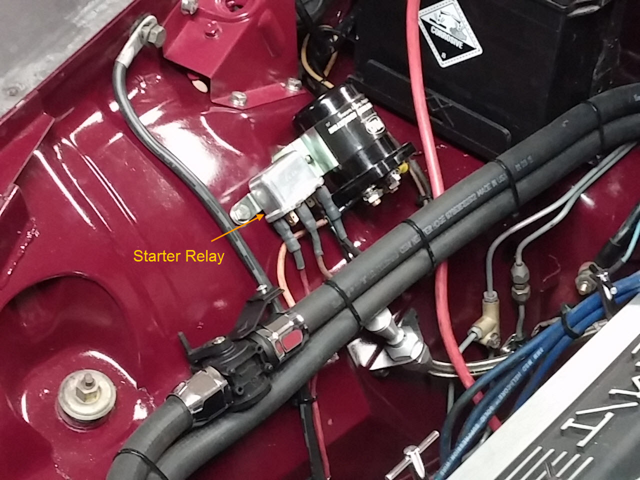
Starter relay next to batter cutout relay


Monday, December 21, 2015

T'was the Weekend Before Christmas!

Dateline - Dec 19, 2015 - Got two solid days of working on the car this week.  I had Thursday off so I could take the other Jag to the insurance adjuster to get an estimate on repairs after the small shunt I had last week (another driver decided they needed to occupy the same spot in the road that I was already occupying!).  I got most of that done pretty early in the day so I spent the rest of the day on Thursday, and all day on Saturday working on the car.  Lots of pictures to show.

Thursday:

First, I sandblasted all the red "anodized" paint that I put on the intake manifold because I really didn't like the look.  After that, I painted it with high heat clear, which made it a solid gray color.  I could have left it natural aluminum, but it would have stained again, so I decided to paint it.

While the paint was drying, I installed the brake pedal, booster, and new master cylinder.  It was an easy install and getting new stainless steel fasteners made thing look really sharp!

Brake Pedal, Booster and Master Cylinder
Next I installed the intake manifold.  I followed the Edelbrock instructions for manifold installation (e.g. throw away the end seals and use RTV instead), however I did put RTV around all the ports.  I know that they recommend that you only put RTV around the water ports, but the heads were not in the best of shape and I didn’t trust that the gasket would seal.  I think if you were working with freshly milled heads, it wouldn’t be a problem, but I didn’t want to have vacuum leaks around the intake ports, so I sealed them anyway.

Then I installed new, angled heater hose outlet fitting to the manifold, and put in all the other plugs and vacuum fitting.  Then I fitted the heater hoses and cut them to shape.

Next I cleaned and installed the distributor.  I’m using the original one that is the HEI type.  Easy to install and all the wiring is already there.  I do have to get a new cape because, when pulling a wire off to reroute it, the connector pulled out of the cap!  So I’m getting a red Mallory HEI one.  This should look really good with all the other red in the engine bay!

While installing the distributor, I found the lock down clamp was really rusted. So I put it through the sandblaster then through the nickel plate bath.  A few minutes with some metal polish and it looked as good as new!

Next I spent some time with the radiator hose spigot.  I’m using the one that was originally on the car, but it was in need of some chrome polish and a bit of filing to get it to mate flush with the intake.  I decided to replace the thermostat (no since in taking a chance).   

That was it for Thursday.

Saturday:
Kicked off the day by installing the carburetor, using a new set of throttle return springs.  I also hooked up the throttle and transmission kickdown cables. This wasn’t very challenging but it sure makes the engine look like an engine!

Next I installed the new billet aluminum fuel filter and new fuel line from the pump to the carb.

Then, I took each valve cover off and spend some time remove the squeezed out RTV from around the gaskets and cleaned each cover and polished the T-Handle bolt downs.  I still don’t know if I’m going to stay with the Mickey Thompson valve covers, but they are an easy swap out if I do decide to change them later.

I then started on some of the wiring.  The fans were the easy first choice because I know which wires were used.  Because I removed the original fan speed resistors and replaced them with the GM version that works with the interior controls, I need to do a little rewiring, but that mainly consisted of changing the wire ends on the fan leads from female to male spades. 

I then spent some time finishing up the brake installation.  I needed to get some brake hose to replace the old ones going from the reservoir to the master cylinder, as well as a bunch of stainless steel fasteners before I could finish things up.  So once I got the supplies, I finished up the installed.  I also needed to spend some time cleaning the reservoir cap and fluid level warning switch.  Got those nice and clean and the hooked up the wiring.

Brakes All Hooked Up Including Booster Vacuum Hose 
Next I spent some time on the wiring on the passenger side.  I have to figure out how I wanted to run the positive and ground cables from the engine.  I also needed to reestablish the ground point on the fender as well as wire in the battery isolation solenoid.  This is a bunch of niggly stuff that takes time and trial, but I think I have most of it figure out.  I do need to get a new ground cable and bit of cable to run from the solenoid to the positive pass through terminal on the body.  So things are not quite done there yet.

Finally, I started working on the last of the wiring.  I did some research and discovered that one relay I couldn’t figure out what it was for is the horn relay!  Yah!  The other two items I need to figure out are if I need the ballast resistor and the Lucas voltage regulator.  I don’t think I need either, but I need to get some time on the internet to figure that out.  Once I have that done, I can finalize all the wiring.

Here are pictures of the completed work from several different angles:

Front.  Note Radiator Hose Routing,  Fuel Filter and Brake Installation

Right Side.  

Top End: Distributor, Carburetor, Water Neck, Shiny Aluminium pulleys
So, outstanding work in the engine area:

Finish wiring
Install new distributor cap
Plumb vacuum lines to the cruise control, vacuum reservoir, and into the car for the air controls,
Install radiator
Install aftermarket fan system (will require some more wiring)
Tie up loose odds and ends
Check all wires, fitting, hose clamps, etc.

I’m still up in the air about what to do with the exhaust manifolds.  They are not on the car yet and I started to sandblast one of them. I just worry that painting them is not going to stay because rust will get under the paint eventually.   I should just sent them in and have them ceramic coated!  I need to make a decision!


Another Productive Weekend

Dateline - Dec 12, 2015 - Had a good Saturday working on the car.  Continued to focus on the engine bay.  I got the parts I ordered from Summit Racing and the red "anodizing" paint for the manifold.  So I got to work.  Installed the new fuel pump, which was pretty easy.  Nice to have clean new parts to put on:

New Fuel Pump Installed

I then focused on installing the battery tray.  I had a plastic tray that I had bought when I first got the car and decided to use that one.  It was much bigger then the battery the car takes, so I cut it down to size and installed it.

Battery Tray and Heater Hoses
Getting prepared for installing the intake manifold meant that I need to clean the heads and block making surfaces.  They still had quite a bit of old gasket and glue on them, so I spent some time cleaning surfaces.

Next I worked on installing the heater hoses.  This was a little work, but I'm happy with how they turned out.  I think I need to make a bracket or two to keep the hoses off the battery.  I will need to make another bracket to move the transmission oil stick/filler away from the firewall.  It's stuck under the heater hoses now and not that functional.

Finally, I started looking at the wiring.  There is a lot of wiring there from the original engine that has been bypassed or is no longer needed.  I'm not quite sure what all of it is about since the engine has been changed twice.  So I need to do some sleuthing to determine if I still need the ballast resister and voltage regulator.  I'm also not sure about the starter solenoid.  I'll figure it out.  I just need to get some time on the Interwebs and work my wiring diagrams.

While I was doing this work, I painted the intake manifold with the special paint.  I had to put down a silver base coat then the red color over the top.  I was feeling kinda "Meh" about the results, but wanted to let it sit for awhile to see if I liked it.

I also painted the brake booster black so that it looks clean and new.

Getting closer!

Monday, December 7, 2015

Back From Thanksgiving Vacation

Dateline – 12/05/2015  I took two weeks off from working on the car to go to California to see family for Thanksgiving.  It was nice to have a long break from work and projects to just relax and enjoy the company of my family.

This weekend I continued work on the engine bay.  I did a lot of odds and ends work since there are just a lot of odds and ends in the engine bay.  Things I got accomplished were:
  • Installed the vacuum accessory tank in the left fender
  • Installed the chassis number plate on the left wheel well
  • Installed the cruise control actuator on the left wheel well
  • Cleaned both through-firewall electrical posts.  These bring positive voltage into the cabin of the car to the fuse block
  • Installed voltage lead that runs between the electrical posts
  • Installed the hood latches including the cable activation system
  • Installed Radiator overflow tank on left wheel well

I was going to install the brake pedal housing and booster but realized that I really want to paint the booster.  I thought it looked good enough after a solid cleaning, but after putting it in the car, I realized it really needs to be painted.  Since the booster and pedal housing need to go in at the same time, needed to wait to put it in until next weekend.

I have also purchased some VHT Red Anodized Color High temp paint (http://www.brandsport.com/vhtp-sp450.html)  I’m going to paint the intake manifold with this to see if I like the results.   I did some research over the holidays and found some pictures of engines that guys have done this too and it looks pretty sharp.   I like the idea of adding some color to the engine since everything right now is polished aluminum, chrome or black paint.  This may be a cheaper way to dress up the engine without needing to buy a polished intake.  If it looks good, I may do the same thing to the Mickey Thompson valve covers.  And if I don’t like it, I can always put it through the sandblaster and get it back to bare metal.  I  LOVE MY SANDBLASTER!

I’m also putting in an order with Summit Racing for a new fuel pump, Russel billet aluminum inline fuel filter, Continental Red Rubber radiator hoses, fuel hose, Spectra Performance Magna-Clamp Hose Clamps and a new battery tray.  I think that is going to give me all the odds and ends I need finish up the engine bay short of the exhaust manifolds.  I still haven’t decided if I want to have these ceramic coated or sand blast then and use high temp paint.  I don’t need to decide right away, but I probably need to get then done soon.

Monday, November 16, 2015

More Engine Bay Work

Dateline - 11/14/2015 -  Spend another Saturday working on the engine bay.  I got the power steering pump pulley cover during the week and put that on.

Next I installed the blower motors/fans.  This took a lot longer than I expected because I had rebuilt and painted the fans over the summer and tested them when I put them back together, but didn't test them with the squirrel cages on them.  Both of them squealed really badly.  Seems that I didn't lubricate the shafts well enough.  So I had to take them apart again, which required unsoldering the leads and brushes from the the windings and and remove a fiberglass board that holds it all together. So what should have been an hour job turned into three, but the fans are in.

Both blower motors/fans installed
Next I put in the windshield wiper motor and apparatus.  I know this was going to be a pain, and it was!  The worst part is that I spend about 1/2 hour looking for the darned bracket that holds the motor to the car.  Couldn't find it anywhere.  Looked in all my boxes in the garages, etc., but no joy.  Then as I was just about ready to call it quits, I remembered it was in the room with all the painted parts!  D'oh!
Windshield wiper motor installed
Windshield wiper shafts and mechanism
Finally, I put a few odds and ends on.  The battery cutout solenoid, the heater water control valve and the automatic transmission filler/dipstick.

Clockwise from upper left: Battery cutoff solenoid, transmission dipstick, heater water control valve  
I had to call it an early day because I was meeting some friends and going to a show.  I will not be working on the car again until December do to other events going on, so my next most will be in a few weeks.


Sunday, November 8, 2015

Engine Dress Up

Dateline - 11/08/2015 - This weekend was focused on engine dress up.  I bought a March Performance billet aluminum Pulley Kit that replaced all the original steel V-Belt pulleys with billet aluminum pulleys, plus new brackets.  I also bought a polish aluminum water pump and a chromed power steering pump.  I spent most of the day doing the installation.

But first, I needed to finish putting in the brake hard lines.  I used marine grade Adel clamps to fasten the tubes down.  Then I cleaned and painted the suspension cross member that runs under the engine.

Brake hard lines running along firewall

Right side brake hard lines

Left side brake hard lines
Suspension cross member prep for painting
Once that was done I started putting the pulley kit on.  I started by installing the power steering pump onto the water pump while it was off the engine.  Then I installed the two pumps on the engine and put on the crank pulley and the power steering pulley and realized I didn't get the pump aligned correctly.  I ended up putting it on and taking it off five times before I got the spacing correct.  It was a pain, but it needed to be correct.

Parts for pulley kit on workbench

Water pump and power steering pump installed on engine (Note painted cross member and sway bar)

Crank pulley, power steering pulley and belt installed
Next was installing the alternator.  I had to removed the original pulley and fan from the new alternator (I had bought it when I got the car in 2009) and install the aluminum fan and pulley.  Then I installed the bottom bracket, the alternator and the upper adjustment turnbuckle. Finally I had to put the water pump pulley on and adjust everything.   It was pretty fast and straightforward.  The one thing I don't like is that the power steering pump pulley doesn't have a cover.  March sells one as an extra and it really needs it. So I purchased the and should have it next week.  Why they don't include it in the kit, I've no idea!

Alternator, water pump pulley and belt installed

View of engine from left

View of engine from right
I'm still up in the air about buying a new intake manifold.  Dropping $375 for something that works fine now is hard for me to justify.  So I thought why not sandblast the one I have and see how it looks.  So I pulled it off the engine and cleaned it up.  I think it is going to work fine.  I am wondering if I should put some high temp clear coat on it to keep it from staining.

Manifold before sandblasting (lines in the middle are an artifact from the camera)

Manifold after cleaning.
 Oh, and this is what fall looks like in my front and back yard!

The waterfall in my front yard

View out my bedroom window

Nice time of year!

Saturday, October 31, 2015

The Jag Is Home!

Dateline 10/31/2015 - The Jaguar has come home.  The tow truck from Precision Tow showed up at Showcase Auto at 9:00 AM on the dot this morning and by 10:00 it was at home in the garage.  Of course, today was one of the wettest we have had in awhile, with serious wind and rain, but it's fall in the Pacific Northwest!  You can't let a little water stop you!  Here are pictures of the car coming home:

Loading car at Paint

Car arriving at house

Getting read to unload
Unloading

Landed in the garage


From the back

Front 3/4 view

Back 3/4 view

Clockwise from top left: Dash vinyl, paint test card, test panel (much lighter than the car really turned out)
 
The bonnet, boot lid, front wings, gas tank covers and doors are still at the point shop.  They will have them for a couple more months while I finish up the inside of the car.  I'm in no hurry to get them back since I'd have to store them someplace.

So now the fun begins! 

After getting the car settled, I spent some time drying it out and removing tape that was left on the car.  I needed to decide which part of the car I wanted to work on first, and decided it will be the engine bay.  I removed the exhaust manifolds to have them ceramic plated.
Exhaust manifolds


I also started putting the brake tubing back in.  It all needed to be cleaned and sandblasted.  I also need to get a bunch of Adel clamps to hold everything down, so things are just hanging right now.

Tubing from master cylinder (upper right) to the front and rear brake connection (lower left)

Left Front brake tube the runs under front body frame

I also pulled out the gas feed hose because it was almost crushed closed! 

Crushed fuel line from engine bay.  Don't know how this car got any gas!
It's going to be so nice put parts back on the car again, AND LEAVE THEM THERE!


Tuesday, October 27, 2015

The Jag is coming home!

Dateline 10/27/2015 - The day has been set!  Saturday 10/31/2015 - Halloween!  The Jag is going to return back from paint!  What an appropriate day to have my red car come home!

Yes, I'm excited!  Last weekend I spent about three hours cleaning the garage so that I'd have a place to put the car!  A summer of parts cleaning, sand blasting and painting, as well as a few home repair projects, had filled up the area the car was in with misclianious stuff.  Plus my workbench had gone out of control.  So, in prep I got everything clean, moved and floor swept, ready for the car to come in.

During the summer I filled up a spare bedroom full of parts that I cleaned and painted.  Everything isn't done, but I really did knock out a great many items, which will make assembly much faster!  Will I be done in a weekend?  NO WAY!  But, with luck, I think I can have it running and on the road by this spring!  That's really cool!

Stay tuned for another update next week with picture of the car coming home!

Monday, July 6, 2015

Mid Year Check-in

Dateline - 07/06/2015 - It's been a long time since I last checked in.  Car is still in paint!  I've been sandblasting and painting every weekend.  That's something I have a hard time doing for more the three or four hours.  It gets old having your hands stuck in the stand blasting cabinet!  But I am making a big dent in the pieces.  I was just amazed at just how many parts there are when I start pulling out the milk crates and boxes.  It's really cool though that I'm building up a room full of cleaned and painted parts.  It will make assembly all that much easier.

I just ordered a zinc/tin electro plating system from Eastwood (http://www.eastwood.com/eastwood-s-tin-zinc-electroplating-system.html).  I've got several parts that really need to be plated instead of painted, so I'm going to give this a try and see how well it works.  Something I haven't done before!

I also found that if you soak parts in undiluted Simple-Green, you can take the zinc plating off of parts that had been plated!  Go figure!

I've also been working on the wood dash.  I shellaced it and when I went to fill in the wood grain, I realized I had not sanded the surface well enough.  Had lots of grooves left over from the flat bed sanding that was originally done to rough out panels.  I hand sanded it and thought I was done, but nope!  So I took out the power hand sander and went at it again.  The nice thing was that the shellac showed all the low spots so I was able to sand it really smooth.  I shellaced it again and started putting coats of lacquer on.  I'm up to 15 coats, but it has been so hot here, even the the mornings, that the lacquer thinner is evaporating too quickly.  I have to wait until it gets a little cooler before I put any more coats on.  Let me tell you, it looks fantastic!

On a whole different subject.  I went to the Northwest Historics vintage races (http://northwesthistorics.com/theguild/upcoming-events/) this weekend with some friends from work and friends of friends and got a chance to do three laps of the Pacific Raceways in the passenger seat of one of the driving instructors for the BMW/Porsche club.  Although we were not "at speed" it was still thrilling to get a chance to go around the track and Doug tried hard to find opportunities to build up a little speed and Gs!  It makes me want to get into "Track Day" events.  Ouch!  This can get expensive quick.  How many hobbies can I afford?  I guess I'll be working until I'm 105!  here are some pictures:


Monday, March 16, 2015

More Sandblasting

Dateline - 03/15/2015 - Did some more sandblasting this weekend.  I'm finding that I can do a 6" x 6" square of metal before the compressor kicks in.  I stop to let the compressor catch up otherwise it just continues to run and I don't want to burn up the compressor or motor.  So, while the compressor runs, I disassemble and prep parts for cleaning.  So, I have now cleaned:

- Radiator cross member
- Coolant header (adapter that goes into the top hose of the radiator to add water and has overflow)
- Boot lid hing springs
- Both interior cooling fan housings
- One interior headlight bucket
- One interior headlight bulb holder ring
- Vacuum reservoir
- Vacuum reservoir bracket

It's a bit slow going, but boy do the parts look nice and will be great when painted!  Much better then sanding by hand, let me tell you!


Monday, March 9, 2015

Dash Work and Sandblasting

Dateline - 03/07/2014 - This weekend I worked on the wood dash with by buddy Matt.  There was one last bit of Maple on the center gauge cluster that needed to be sanded down and finished.  Matt has great wood working tools and with the help of his belt, rotary and drum sanders, as well as his band saw, we were able to whip it into shape.  Now it finish time!

I spend part of Sunday the finishing touches to the air compressor by drilling holes in my garage floor and mounting the compressor so that it doesn't walk around.  After getting it set up, I put sand into my blaster cabinet, hooked up the air and started sandblasting.  My first piece was the cross member that holds the radiator in the car. This barely fit in the cabinet, but it was a good piece to practice on and after about 45 minutes I got it pretty well cleaned up (see pictures).  

Cross member with just a little sandblasting

Cross member completely sandblasted

I also cleaned up the radiator filler which took less then 10 minutes (no pictures).  Now I have an idea on how long it will take to do some of the parts and need to start digging around in my boxes for things clean up.  I'm pretty exited.