Tuesday, February 9, 2016

Lights! We have lights!

Dateline - 02/06/2016 - Continued working on the back of the car this weekend.  My first effort was to get the tail lights and side markers installed.  This required getting some more hardware and the correct tap to clean up the paint and body filler encrusted holes.  In order to not mess up the paint on the car, I had to really take my time so it took a little longer then I thought.  I have to say, it really looks good to have the tail lights back on the car:

Right rear side marker
Right rear side marker lit
Rear of car with tail lights and trunk seal.  Note wires coming out the back of the body are for the license plate light in the bumper.
After getting the lights done, I found the two wooden panels that sit on the floor of the car to cover the fuel system and spare tire and pulled the metal parts off of them, or at least tried to.  They are really rusty and I wasn't able to free some of the parts, so I'm going to need to grind the heads of the screws off.  I wasn't feeling like doing that on Saturday, so they will have to wait, but the parts I did get off I sandblasted and painted.  I think I'm going to try to find new plywood eventually since I'm going to re-upholster the entire trunk at some point, but for now, I'm going to use what I have.

I also started work inside the car!  Yes, moving to the big job!  I installed the gas peddle arm and adjusted the cable linkage to the carburetor.  I installed the new plastic gas pedal (I'm ditching the chrome foot I had before.  Also, I installed a few brackets under the dash and routed some wiring.

I was still feeling a bit under the weather with my cold, so I didn't put a full day into it, so that's as far as I got.  The plan is to continue with the drivers side wiring, installing the steering wheel including the linkage at the rack, and to start putting in upholstery!  It's coming along!

Monday, February 1, 2016

No Work on Car This Weekend

Dateline - 01/30/2016 - Did not work on the car this weekend.  I have been fighting a cold all week and decided that working on the car in the cold garage was probably not the best way to get over it.

Instead, I went over to the Kingston area and met up with my friend Roland to talk to a guy who champions a car in the LeMons races (https://en.wikipedia.org/wiki/24_Hours_of_LeMons) in the local area.  He is looking for a driver/wrench turner and Roland thought I would be interested.  The fact that they are driving a Rover P3500 with a supercharger is beside the point. This seems like a really fun and low cost way to try out racing.  You can race for as much as two hours at a stretch, so you get a lot of wheel time!  Still thinking about this, but I'm very, very interested.

Back to the car, I did get the gaskets that I ordered the prior week, so next Saturday I should be able to put some time into the car.

Tuesday, January 26, 2016

Finished Trunk - Mostly

Dateline - 1/23/2016 – Continued to work on the truck on Saturday.  I needed to tie up loose hoses and get the wiring settled out.  I installed waterproof connectors on all the wiring for the taillights and side markers and was planning on installing them, but when looking through my box of parts, I realized that I had ordered the gaskets that go between the lens and the light frame, but not between the frame and the car!  Do’h!  So I ordered the parts via SNG Barratt and hopefully they will be here soon.

Also, I installed the boot lid seal and hinges and generally cleaned up the trunk.  At some point in the future, I’m going to install upholstery panels and such, but that is a task for another time. Right now, I’m happy to have all the wiring done and ready to go.  


Here are some pictures.  It's come a long way since this: http://leapingv8s.blogspot.com/2009/10/down-for-winter.html
trunk from back looking forward

View from passenger side
View from driver side

Top view of fuel control system (top is forward)

Vapor recovery system.  Not how tubing runs up the driver side C pillar.

Monday, January 18, 2016

Started On The Trunk

Dateline – 1/16/2016 – Finished up under the hood and started work on the trunk this weekend.  I had a few odds and ends to do under the hood, like putting on some hose clamps, finalizing some hose and wire routing and hooking up the water control valve for the heater.  

If you go back to Jan 14, 2014 (Wow!  Two years ago!) http://leapingv8s.blogspot.com/2013/01/starting-work-1-item-at-time.html  you will see that I created a system that uses a Chevy Astro vent door actuator to activate the heater water control valve mounted in the engine bay.  That actuator is not heat resistant so it needed to be mounted in the inside of the car, so I mounted it on the brackets I build to hold up the right side dash board and the new fuse blocks.  The activation cable runs a straight shot through the firewall right to the water heater value. 

Except for the exhaust manifolds, and a few things I need to do once I have the hood installed, I’m think I’m done with the engine bay!  Yes!!!

I also started working on the trunk.  First, I had to paint the area around the back on the trunk that was still in primer.  After getting that painted, I installed the fuel tank manifold system.  If we go back to October 28, 2013, http://leapingv8s.blogspot.com/2013/10/welcome-to-20132014-project-car-season.html you can see the tank delivery system I devised.  I took all of this out when I got the car painted, so I reinstalled it this weekend.

I also needed to put in the interior air circulation box.  Every car has places that allow the air inside the car to exit out so that you do not build up pressure inside.  On my car, the exit points are in the rear trunk lid crease.  The air travels through a vent in the top of the rear deck (seen here http://leapingv8s.blogspot.com/2011/12/great-movement-forward.html), into a box about 1 1/2 inches deep under the deck.  This box was really rusty so I cleaned it up and fiber glassed it (http://leapingv8s.blogspot.com/2013/03/odds-and-ends-and-odds.html).  In October, I mounted the four, one-way doors using Kevlar fabric (the original was rubber impregnated silk).  Here are pictures of the finished item out of the car:

Air circulation box outside of car, clean and painted.

One way doors as seen from car side of box.

One way doors as seen from trunk side of box.

To mount it in the trunk, I needed to put a seal around the mating surfaces and then carefully bolt it back in.  I created the seal using Eastwood Flexible Strip Caulk (http://www.eastwood.com/ew-flexible-strip-caulk-bk-2-lbs.html) because I knew it would make a good seal and would conform to the surfaces.  After getting the box installed, I ran tubing from the vents (the things that plugged up and caused the box to rust in the first place) through the trunk and out a hole to the rear wheel well.

Next I needed to put in the fuel vapor control system.  This system is very interesting.  There are two vents on each gas tank.  One is at the top of the tank, the other runs from the filler nozzle.  The one on the tank allows air to enter the tank and keep it from developing a suction.  The one on the filler is used to catch any gas vapor the exits the tank.  These two vents connect, via tubing to a manifold that sits against the back window base and then runs up the left side C pillar, then back down to the trunk where it exits into a tube that runs to the engine bay.  The manifold is designed so that if any liquid gas gets caught in the lines, it will drain back into the tanks, ensuring that the line stays free for vapor to flow through.

Over the summer, I had sandblasted and painted the pipes.  Now I had to reinstall then.  It was a bit tricky because I had done a lot of work on the back deck, so I needed to drill some holes to allow the pipe to go through.

That was as far as I got on Saturday.  I don’t have much left to do in the trunk at this point:

  • Wire up the fuel control solenoids
  • Install the tail lights and wire them
  • Plug in the fuel gauge senders
  • Install the truck fuse block (I added this so that I can put in electronics in the back if I want)
  • Install the tail lights
  • Clean up the loose wiring.
  • Install the trunk hinges


Monday, January 11, 2016

Engine Bay Odds and Ends

Dateline 01/09/2016 – Did lots of engine bay odds and ends this weekend.  The day started with installation of the fan control unit.  I did opt to purchase a thermostatically controlled unit from the same company that made the fan.  I mounted it on the firewall where I had the relay before.  It requires a probe be pushed into the fins of the radiator, on the other side of the car!  So it took a little finagling to find a place that was close to the battery and still had enough length to reach the correct spot on the radiator.   Here is the installation of the probe:

Temperature probe (brass cylinder just to the left of fan shroud) installed on hot side of radiator
To wire in the controller, I had to mount a 30 amp circuit breaker (which I put beside the battery) along with wiring from the battery controller.  I also had to run a hot from ignition and an override wire back into the car.  This required making up some more wiring harnesses and since I was in the same place as the windshield washer reservoir, I went ahead and wired that up too.

The original instructions had the fan leads being spliced directly to the controller, but I didn’t like this idea because I would have to cut off the splices if I ever needed to remove the radiator.  So I use a three prong waterproof connector that I purchased many years ago to give me easy disconnection.

The final effort in wiring was finishing off the wiring around the battery cutoff relay. I needed to purchase a battery cable that would go from the relay to the firewall pass-through stud, which I got from Amazon.   The rest was wire wrapping and clean-up. 

So, all I have left for wiring in the engine bay is connecting the distributor and the fan controller to ignition hot, which will happen inside the car.  Honestly, I’m glad to be done with wiring for a while!

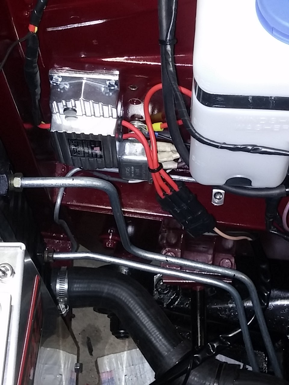
My next project was fitting the radiator.  One of the things I didn’t like about the prior installation was the transmission cooling lines.  They were in pretty bad shape, looking like they have been used for a couple of different engine installations.  So I purchased some steel tubing, a double flare kit and a tubing bender and went to town.  Here is a picture showing the tubing, the fan controller, the horn relay, and the windshield washer bottle.
Fan Controller and new radiator cooling tubing  Note plug connecting wires from controller to fan

Once I got the tubing bent, installation of the radiator was easy.  Just needed to screw in the top bracket and it was done! 

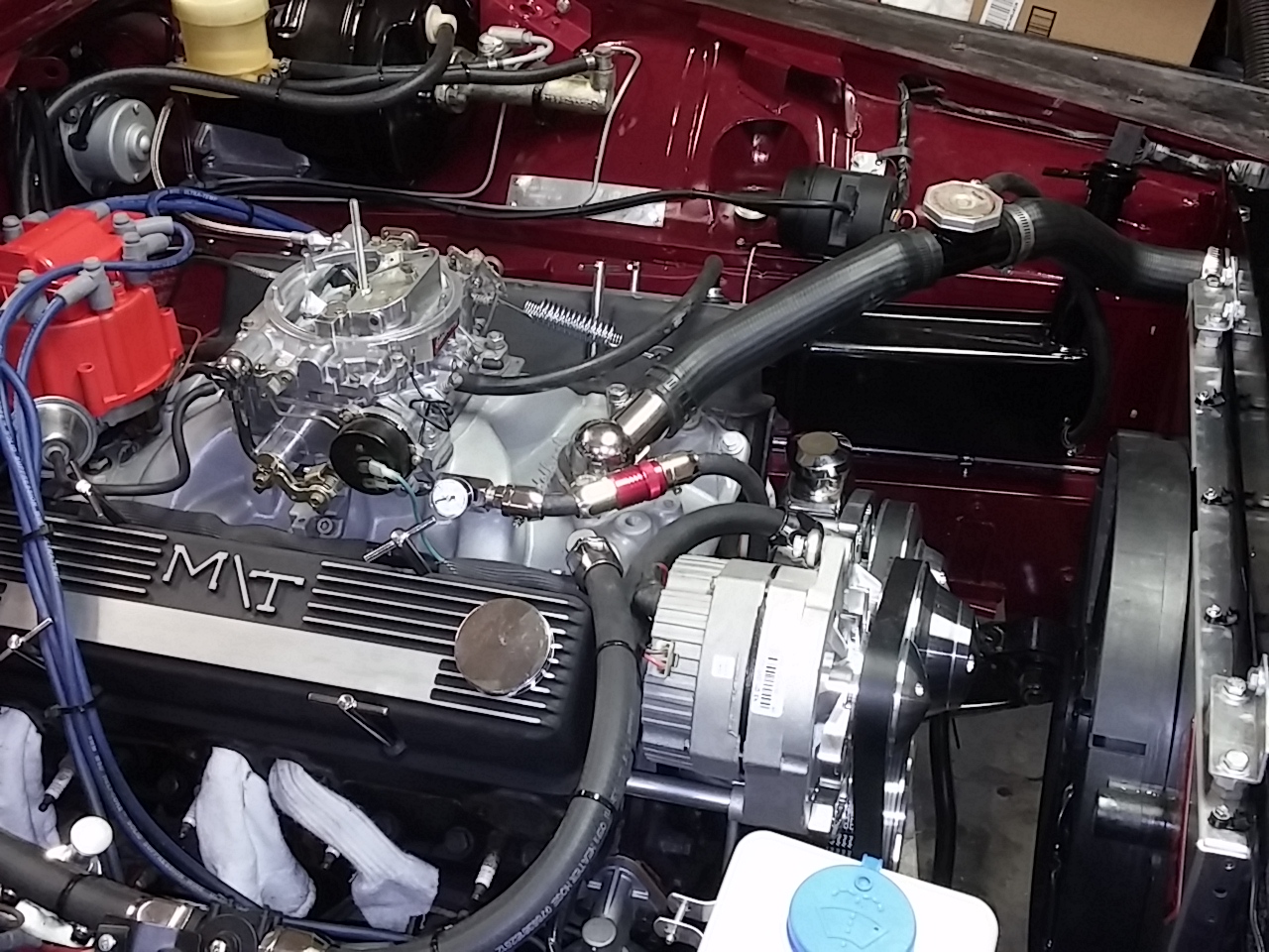
My last task of the day was to install the thermostat housing and radiator hoses.  I bought new stainless steel bolts to hold in the housing, so it was an easy matter of installing it.  I put the radiator hoses on, but I need to get a few hose clamps.  I also installed the radiator overflow from the filler cap to the overflow tank.  I do need to get some more radiator overflow hose to go from the overflow tank to the ground.


Thermostat housing, upper radiator hose and overflow hose to overflow tank.
So, what’s left?   Well outside of the elephant in the room, the exhaust headers, not much.  I have a little more strapping and tidying to do, a few holes to plug and some wiring to complete inside the car, but honestly, the engine bay is done!

Next week, I start the trunk!

Monday, January 4, 2016

Welcome 2016!

Dateline – 01/02/2016 – Did a lot of fabrication in the engine bay this weekend.  Fabrication always takes a long time and it never feels like I get a lot done after an eight hour day, but the reality is that I do.  So what did I fabricate?  A bracket to keep the heater hoses from resting against the battery.  A bracket to move the transmission fluid filler/dip stick away from the wheel well to clear the heater hoses and a bracket to hold the new, generic fit, windshield washer tank/pump.  All required, templates, cutting, drilling, filing, sandblasting and painting.  Like I said, a lot of work, but well worth the effort.

Bracket to keep heater hoses away from battery (hard to see but its there!)
Bracket to move transmission oil filler/dipstick way from wheel wheel to clear heater hoses
I got most of the windshield washer installed but it was getting late so I wasn’t able to finish the wiring.
Windshield washer tank and pump installation
I also installed a new battery ground cable and put rubber hoods over both the battery ground and positive cable to clean them up. 

I finally tore apart the old voltage regulator wire harness and realized that none of the wires are used at all, so pulled the regulator off and attached the harness to the wheel well for safe keeping.
Voltage regulator wire harness bundled out of the way.
I also finished the electric cooling fan installation.  It required another run to the hardware store for longer bolts and a bit more drilling.

Last but not least, I installed all the vacuum hoses inside the engine bay.  I’m using the original A/C Overflow tank that is installed in the left wing as a reserve vacuum tank which is recommended with the vacuum actuated cruise control.  The vacuum out port on the manifold has two pipe fittings.  I used one for the vacuum advance on the distributor, the other for the vacuum to the cruise control and to actuate the vacuum motors that control airflow in the car.  The car originally had a vacuum motor controlling the vent/re-circulation gate, so there was already a port in the firewall to allow the vacuum hose to pass through, so that was pretty easy routing.

So, what is left?  Not much actually!
  • Finish wiring in the windshield washer motor
  • Finish wiring in the battery cutoff relay and bundle up the wiring harness
  • Finish wiring in the electric cooling fan.  I think I’m going to get a temperature activated fan controller so that the fan only come on when the radiator gets to a set temperature.  That will probably get rid of the relay I have mounted now.
  • Wire in the Distributor to “hot from ignition.”  I need to find a wire inside the car for that.
  • Final wire harness bundling, holes in firewall filled and cleanup.
  • Exhaust manifolds. 


Monday, December 28, 2015

Christmas 2015

Dateline - 12/24 and 12/26 2015 - I had two solid days on the car over Christmas break and got a lot done, although it really doesn't look like it from pictures.

Thursday 12/24/2015:
First thing I wanted to do was re-route the fuel line to the carb.  I didn't like it being so close the the heater hoses, so I moved it around to the other side.  Next I put the hose clamps on the heater hoses.  I purchased hose clamps that have chrome anodized aluminum fitting that make them look like pressure fittings.  It's a bit of bling that looks so much better then plain old hose clamps.  I also put on the new distributor cap, which required removing the HEI coil and plug wires from the old one and installing them into the new.  Simple swap but I like the looks much more than the black cap that was on there.

That was all the easy stuff! Next I decided to tackle the wiring.  I've been holding off on this because I knew it was going to be a bear and I wasn't disappointed!  All the original wiring was left in the car after the engine swap out.  A wiring harness that came with the engine swap kit interfaces between the old and the new.  I wanted to get rid of the old wiring that wasn't needed, so I had to figure out how it worked as installed.  It took me several hours of tracing wire, looking at schematics and puzzling over what I had in front of me to figure it all out.

The first puzzle was the starter relay.  This had all the original connections, but some had been removed by someone (me) who did not mark the wires (DUMB!) so I wasn't sure how things needed to go back together.  I had to split apart the wiring harnesses and pull apart connections in the car to trace where all the wires went.  The key was finding the wire that goes from the ignition switch START to the relay.  Because of my extensive re-wire and the the wire color code changing between the engine bay and the inside of the car (Jaguar!) this was no easy feat.  I ended up spending about 1.5 hours with an ohm meeting probing at wires until I figured it out.

Next I had the find the Starter Isolation switch wire which breaks the ground side of the starter relay.  This switch is mounted on the gear shift and is only activated when the car is in Park or Neutral.  This way you can't start the car while in gear.  20 minutes with an ohm meter and I found the wire.  So, now I had everything I needed to hook up the relay.

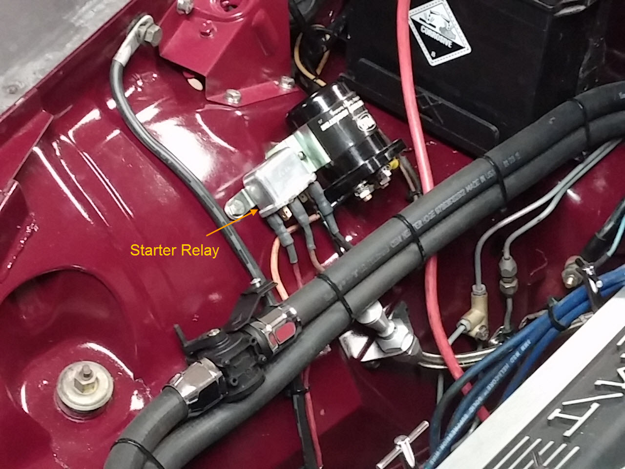
But of course, I couldn't put a nasty old corroded relay back into the car.  So I spend some time with some metal polish and shined it up to a nice bright gloss!  Then I mounted the relay next to the battery cutout relay, plugged in the wires and voila!

My next challenge was the wiring harness going to the engine.  This thing was nightmare.  This is a harness that come with the engine swap kit so it has a plug that plugs into the existing wiring harness, which is good, but it also has a bunch of extra wires for different Jaguar installations and I had to figure out which were originally used.  I basically needed three wires: 1) A hot wire going from the ignition to the distributor "BAT" terminal, 2) A wire for the oil pressure sender and 3) a hot wire to the automatic choke on there carb.   Once I figured out those wires, I was able remove the unneeded wires, which reduced the complexity quite a bit.

From the alternator, I have the hot wire that goes to the battery, which doesn't use the existing wiring in the car.  Instead a large lead runs from the alternator, across the top of the engine and out the back to the right side hot connection terminal on the firewall.

The alternator also has a plug that has two wires.  One is a hot that energizes the alternator the other is a wire that goes to the "ignition warning light" on the dash.  The hot was easy (just used what was there before) but the ignition warning lamp had me scratching my head because I could not see this ever being hooked up.  It had a bullet connector and there was no wiring in the car where this would fit.  So I'm thinking it was never hooked up.  So I covered the bullet connector and buried the wire back into the harness. I figured if I need it, it will be there and I can easily pull it back out.

While working on this harness, I had a nagging question running in the back of my mind.  "What about the tachometer?"  My experience with cars has been that the tach usually uses a wire that connects to the coil to sense how often the coil is firing.  Well, the HEI unit has a "TACH" plug, but the existing wiring harness has no wire connected to that.  This meant that the tach was getting a signal from someplace else.

Now the real head scratching began.  How did the tach work?  I had to figure this out because I have an aftermarket tack to put in and need to make sure it gets wired in correctly.  When I look at the wires and trace things down, I have a wire running from the tach to one side of the ballast resistor.  On the other side of the resistor I have two wires ganged together, one that runs to the HEI unit and other that goes to the starter relay which I had disconnected as not needed (see above).  How did all of this work? Finally it occurs to me.  Instead of running a hot from the ignition to the ballast relay, to the coil, and another wire from the coil to the tach, Jaguar ran the hot from the ignition through the tack, through the ballast relay, to the coil. This reduced the amount of wire needed.  Of course, if you ever remove the tach, the engine wouldn't run, but who would ever do that?

But what about the hot lead coming from the starter relay going to the coil side of the ballast resistor?  To answer that, we need to review the principles of coil based ignition systems (believe me, I had to look all this up!).  The average coil only needs about 9 volts to operate effectively.  If you run a coil at a constant 12 volts, you will overheat the coil and cause premature failure.  So, to get the maximum life from the coil, you need to step down the voltage.  The easy way to do this is a resister placed in series.  Thus, the ballast resister was born.

But why put 9 volt coils in to begin with?  Why not make then 12 volts?  Hearken back to the days of yor when cars had very low tech carburetors, suspect fuel quality and low compression engines.  Remember, you need three things to get an engine to run, fuel, compression and spark.  In the above scenario, two of the three things you need are poor (fuel and compression).  So what can you do to help the engine start?  Have a very hot spark.  And how would you do that?  Over-energize the coil!  So, in many cars, there is a bypass wire that goes from the starter relay to the coil that will put 12 volts to the coil when the engine is being started to get a hotter spark.  As soon as the car starts, the coil voltage dropped back to 9 volts and everyone is happy. Pretty ingenious actually!  Now this is all fine and good when you have a coil.  HEI systems don't need the power reduction so I could get rid of the ballast resister.  That left me with a spare wire running from the starter relay to the now missing ballast resister.  I'll get back to this wire in a moment.

But I still have a problem.  My tach needs a separate power and tach signal to work.  So, I took the original wire that went from the tack to the HEI unit, cut it and connected it to an unused wire in the new wiring harness and plugged that into the TACH pin of the HEI unit.  I then spliced the HEI BAT wire into the now unused wire that went starter relay/ballast resister which will go to ignition hot (yet to be determined).  So, this should give me hot when the ignition is on, a tach signal and removed the ballast resister.  What a pain, but boy did I feel good once I got this figured out!

My next challenge was mounting the horn relay.  Not too bad.  Of course, I had to polish it too so that it had the right look!

That was enough for one day!

Saturday, 12/26/2015:
More wiring!  I decided to focus on the bunch of wires I have on the left had side of the car.  Here I have:

  • Transmission torque converter lock relay signal
  • Speedometer sensor power and signal
  • Cruse control magnet pickup wires
  • Oil pressure sender
  • Water temperature sender


Everything but the water temperature sender needs to be bundled and run across the top of the firewall, then down into the transmission tunnel.  The oil pressure sender wire comes out of the bundle part way down to run across the gap between the firewall and engine.  This was all pretty straight forward.  I may not need the Cruse control magnet pickup wires if I can successfully get the signal from the tachometer.  I still ran the wires, just in case.  If I don't need them, I'll strap everything up under the car.

I also had a wire to run to the water temperature sender which needed to be wrapped up with the wires going to the cruse control.  I had already wrapped those wires, so I needed to unwrap and re-wrap them.  I hate doing things twice (or three or four times) but it needs to be right.

I next spent some time installing the cruse control linkage.  Since I already have a lot of linkage for the throttle and transmission kick-down, it was a pretty easy go to drill a hole in the brackets and install the cruse control linkage.  The kit came with a lot of options and I was able to use the easiest method.  Nice to have something easy for a change!

My next challenge was the radiator and electric fan.  As with most aftermarket items, the fan did not quite fit the radiator (a little small), so I had to spend a couple of hours "engineering" a solution.  The kit came with brackets that I was able to use with plenty of spacers, but unfortunately the bolts I have are not long enough.  So, I need to make a run to the hardware store for some more!

I also needed to wire up the fan. There three ways to do this.  I can wire it to be full speed all the time,  slow speed part time and full speed when needed, or off until a temperature is reached, then slow speed until it reaches a higher temperature then full speed.  The last two require a thermostat that I don't have.  I like the idea and will probably get the thermostat, but right now I wired it to be full speed all the time.

I also need to find a 20 amp hot to power the fan, and a hot from ignition to run the fan relay.  I didn't get that far though.  I did get the relay polished up and mounted.  After that, I was done for the day.

BTW - You may be asking what about the voltage regulator?  It's still hanging out there (literally).  I've not decided if I want to leave it in or not.  I'm thinking yes, but I'm still undecided.

Here are some pictures.

Getting Closer.  Radiator fitted.  Note new routing for fuel inlet hose/filter and the anodized hose clamps

Right side view

Right back 3/4 showing electric fan

Left side view.  Note cruse control linkage (black cable) between throttle (top) and transmission kick-down (bottom)

Horn and fan relays on right wheel well next to radiator

Starter relay next to batter cutout relay