Dateline - 04/28/2013 - Took Saturday off because I wasn't feeling well, so worked on the car 1/2 day on Sunday. Again, more wiring, but I'm really making headway! I have all eight switches that go into the center console wired and tied off! YES! Now I have two switches that go on the left lower facia (Master Power and Headlight Override) to wire, but I need to order the connectors. I also have the digital dimmer switch to finish up. I printed the box for it on my 3D printer on Saturday, so now I just need to wire it up. I have to change the instrument light wiring that I created last year because I need to run the ground back to the switch, not to the chassis as I had originally ran it. That gave me a chance to clean up some of that wiring too.
So what is left? Wiring the fuse box in the trunk, dimmer switch, and cleaning up the remaining wiring harnesses. Wow! I'm really getting there! Yahoo!

Monday, April 29, 2013
Monday, April 22, 2013
Why Can't The Wiring Be Done Already!
Dateline - 04/20/2013 - Another full day of working on wiring. Boy-o-boy is this getting old! The good news is that I've rerouted all the wires the way I want them, and laced them all together. I left off with making up the wires for the switches. I know how long they need to be and have them all ready to go, but ran out of steam at 5:00 pm. So now, all I need to do is make up the switch connectors. I do need to do some rewire for the instrument lights because I bought a digital dimmer control, but that shouldn't take too long. I still have to sort out the wires running to the trunk on the drivers side of the car. I also need to mount my new fuse block in the trunk. But it's coming down to brass tacks now.
After I got done working on wiring, I went into the house and did some more work on the rear air recirculation box. Several posts ago I reported that I scrubbed away a great deal of the rust and fiber glassed the holes. This weekend I put a nice clear coat of resin to fill in any gaps. I also took about the three remaining flapper doors and cleaned then up and rust sealed them. I need to make one flapper door out of some sheet steel, then find a good replacement fabric for the hinges. Yes, the original used a rubber impregnated silk as a hinge! I think I'm going to get a good ripstop nylon or Kevlar.
Well, that's it for this weekend!
After I got done working on wiring, I went into the house and did some more work on the rear air recirculation box. Several posts ago I reported that I scrubbed away a great deal of the rust and fiber glassed the holes. This weekend I put a nice clear coat of resin to fill in any gaps. I also took about the three remaining flapper doors and cleaned then up and rust sealed them. I need to make one flapper door out of some sheet steel, then find a good replacement fabric for the hinges. Yes, the original used a rubber impregnated silk as a hinge! I think I'm going to get a good ripstop nylon or Kevlar.
Well, that's it for this weekend!

Monday, April 15, 2013
Little Work This Weekend
Dateline - 04/14/2013 - I didn't do much work on the car this weekend. I had to take care of the other Jaguar. It needed a 90K mile service, plus an emissions test and new tabs. Took care of all that (and got a haircut, no, a real haircut, to boot!). That was most of my Saturday. I did try do some work with my 3D printer that was car related though. I'm trying a new type of plastic called ABS instead of PLA in my printer. PLA is easy to print with because it heats at a lower temperature (185 degrees) and doesn't warp a lot. ABS needs about 230 degrees and a very warm bed to print on (around 110 degrees) otherwise, it will warp, which makes it much harder to work with. The advantage of ABS is that it is not biodegradable like PLA. So, I want to make sure that any parts I build that will be on the car are in ABS not PLA.
The problem I've found is that my hotbed will only go up to about 80 degrees, not hot enough to keep the ABS stuck to it, so when it warps, it actually detaches from the bed and ruins the print. I need to do some research to see if I can get the hotbed hotter. I've seen a couple of blog postings about that, so we shall see.
Another car related 3D item is the center indicator bezel was printed in PLA and I want to print it in ABS. The problem is that I lost the model I used to create the original because of a hard drive failure. So I spent about two hours on Sunday recreating the model. Tedious! And I really hate doing things a second time. But that's what you get for not doing enough backups!
So, not a very productive car weekend. But I'm going to try to spend some time after work this week to get some stuff done. Looks like it will be warming up a bit this week, so that will make it easier to go out in the garage!
The problem I've found is that my hotbed will only go up to about 80 degrees, not hot enough to keep the ABS stuck to it, so when it warps, it actually detaches from the bed and ruins the print. I need to do some research to see if I can get the hotbed hotter. I've seen a couple of blog postings about that, so we shall see.
Another car related 3D item is the center indicator bezel was printed in PLA and I want to print it in ABS. The problem is that I lost the model I used to create the original because of a hard drive failure. So I spent about two hours on Sunday recreating the model. Tedious! And I really hate doing things a second time. But that's what you get for not doing enough backups!
So, not a very productive car weekend. But I'm going to try to spend some time after work this week to get some stuff done. Looks like it will be warming up a bit this week, so that will make it easier to go out in the garage!
Monday, April 8, 2013
Starter Circuit and More Wire Cleanup
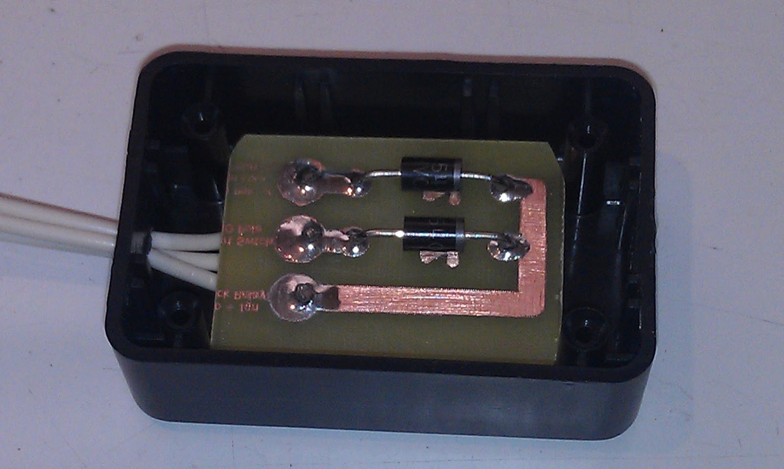
Dateline - 04/06/2013 - Spent Saturday putting together my starter circuit. I did some work on this several weeks ago but was not happy with the results. I had soldered two diodes in line with the actual wire and I was thinking that is just an open circuit waiting to happen! So I etched a little circuit and mounted it in a box from radio shack:


After I put that together, I mounted it under the dash and re-wired the four relays. It took longer then I expected it would take, but I got everything working and tested. It's going to be cool to have the power and start buttons on the center console!
The rest of the day was spend doing wire clean-up. One thing is for sure, if I ever do this again, I'm going to spend more time running wire in a clean fashion while doing the work instead of tying to do it after. Going back and doing cleanup really sucks! I've probably wasted about 100 slices just cutting and re-cutting! "If you can't find time to do it right, when are you going to find time to do it over!"
By about 6 pm I was done. I was feeling a bit under the weather, so I called it a day.

After I put that together, I mounted it under the dash and re-wired the four relays. It took longer then I expected it would take, but I got everything working and tested. It's going to be cool to have the power and start buttons on the center console!
The rest of the day was spend doing wire clean-up. One thing is for sure, if I ever do this again, I'm going to spend more time running wire in a clean fashion while doing the work instead of tying to do it after. Going back and doing cleanup really sucks! I've probably wasted about 100 slices just cutting and re-cutting! "If you can't find time to do it right, when are you going to find time to do it over!"
By about 6 pm I was done. I was feeling a bit under the weather, so I called it a day.
Monday, April 1, 2013
Wire, Wire Everywhere!
Dateline - March 30-31, 2013 - Worked more on wiring this weekend. First, I wanted to check out the wires that run to the trunk for the old fuel pumps, which I'm going to use for the fuel shutoff valves. I found the wires intact, but I did find a short in the right hand wire where it had rubbed against the rear finder well. I'm surprised this never blew a fuse when the fuel supply switch was set to that tank. That tank was out of commission (leaking) for a long time, so it just may never have happened, but I'm glad I found it!
Next, I wanted to install the oil pressure switch that I ordered so that I can turn on/off the starter switch light. Turns out there was already one installed on the car! Should have checked that, but it makes total sense because there is a low oil pressure light on the original! So, that was easy!
I then decided to formalize the relay area in the dash more by taking out the relay frame I made and painting it. This required that I pull all he relays out. While there I also did some cleanup by shortening some of the wires from the aftermarket headlight kit.
Next I started working on cleaning up the main wiring loom to the fuses. As I mentioned before, I need to move the original fuse boxes from in the middle of the dash, behind the gauges, to the right had side of the dash behind what will be the new glove box will be. I also wanted to upgrade to the new type of fuses while I was at it. This is a pretty easy job because the wires going to the original fuse boxes were held in with standard female spade connectors. All I had to do was mark each wire, pull the fuse boxes out, make new wires with the male spade connector and run the wire to the new location. I did that last spring and was holding everything together with nylon zip ties until I got all the wiring sorted. Well, now that the wiring is pretty much done, I wanted to start cleaning up. So I pulled the wires from each side of the of the fuse boxes and laced them up nice and neat. This took a lot of time because I wasn't careful about how I ran the wires to begin with (lesson learned!) so I had to pull wires rearrange them and then lace them up. Once I was done, I had four nice tight bundles of wire instead of one big honking one!
After doing all the lacing, I realized that the wires, were all too long! Unfortunately, I didn't have any more spade connectors, so I pretty much left them until Sunday when I was able to get more at the store.
The rest of Saturday evening was spent cleaning up the wire harness that runs along the right side rocker panel. I added a few wires including +12 volt hot to the trunk, and all of these needed to be taped together and run through a couple of sections of the body (that's when I discovered the shorted wire!)
Saturday night I worked on covering the bottom glovebox in 3M carbon fiber vinyl. Looks pretty good!
Sunday I went to the local hardware store and got a bunch'o connectors and started pretty much finished up the wiring to the fuse boxes. I had some concerns after working on all the wiring that I may have some miss-connected, so I took a lot of time with an ohm meter and the wire diagram to make sure I had things right. I found out that I actually did have a couple wrong, and one main source was missing to the headlights. I got that all cleaned up now. I have to get a few multi-connector adapters at the local auto parts store and then I'm pretty much done. I'm very happy with the wiring and how it turned out. Much cleaner then I was hoping for.
So, just to add some balance to my life, I didn't work on the car all weekend! I did mow the lawn for the first time this year! I always try to wait for Easter weekend to mow for the first time. I will be mowing it every week from now until August when it drys out and pretty much stops growing, so I like to delay it as long as possible! If you can't tell, I don't like mowing the lawn!
So, still moving and making small steps. I'm waiting for some connectors to come in the mail and I have some more circuit board work to do before I can finish the power/start switches. I will work on that this week until I head to Forks to go fly fishing on the Hoh River!
Next, I wanted to install the oil pressure switch that I ordered so that I can turn on/off the starter switch light. Turns out there was already one installed on the car! Should have checked that, but it makes total sense because there is a low oil pressure light on the original! So, that was easy!
I then decided to formalize the relay area in the dash more by taking out the relay frame I made and painting it. This required that I pull all he relays out. While there I also did some cleanup by shortening some of the wires from the aftermarket headlight kit.
Next I started working on cleaning up the main wiring loom to the fuses. As I mentioned before, I need to move the original fuse boxes from in the middle of the dash, behind the gauges, to the right had side of the dash behind what will be the new glove box will be. I also wanted to upgrade to the new type of fuses while I was at it. This is a pretty easy job because the wires going to the original fuse boxes were held in with standard female spade connectors. All I had to do was mark each wire, pull the fuse boxes out, make new wires with the male spade connector and run the wire to the new location. I did that last spring and was holding everything together with nylon zip ties until I got all the wiring sorted. Well, now that the wiring is pretty much done, I wanted to start cleaning up. So I pulled the wires from each side of the of the fuse boxes and laced them up nice and neat. This took a lot of time because I wasn't careful about how I ran the wires to begin with (lesson learned!) so I had to pull wires rearrange them and then lace them up. Once I was done, I had four nice tight bundles of wire instead of one big honking one!
After doing all the lacing, I realized that the wires, were all too long! Unfortunately, I didn't have any more spade connectors, so I pretty much left them until Sunday when I was able to get more at the store.
The rest of Saturday evening was spent cleaning up the wire harness that runs along the right side rocker panel. I added a few wires including +12 volt hot to the trunk, and all of these needed to be taped together and run through a couple of sections of the body (that's when I discovered the shorted wire!)
Saturday night I worked on covering the bottom glovebox in 3M carbon fiber vinyl. Looks pretty good!
Sunday I went to the local hardware store and got a bunch'o connectors and started pretty much finished up the wiring to the fuse boxes. I had some concerns after working on all the wiring that I may have some miss-connected, so I took a lot of time with an ohm meter and the wire diagram to make sure I had things right. I found out that I actually did have a couple wrong, and one main source was missing to the headlights. I got that all cleaned up now. I have to get a few multi-connector adapters at the local auto parts store and then I'm pretty much done. I'm very happy with the wiring and how it turned out. Much cleaner then I was hoping for.
So, just to add some balance to my life, I didn't work on the car all weekend! I did mow the lawn for the first time this year! I always try to wait for Easter weekend to mow for the first time. I will be mowing it every week from now until August when it drys out and pretty much stops growing, so I like to delay it as long as possible! If you can't tell, I don't like mowing the lawn!
So, still moving and making small steps. I'm waiting for some connectors to come in the mail and I have some more circuit board work to do before I can finish the power/start switches. I will work on that this week until I head to Forks to go fly fishing on the Hoh River!
Monday, March 25, 2013
So Much To Do, So Little Time In The Day!
Dateline - March 23, 2013 - Only worked on the car on Saturday this weekend. Did lots of odds and ends stuff.
- Modified and left hand fuel level sender. Now I have both sides done. I have also ordered and received all the seals (Filler neck, drain plug and fuel sender) and two lock rings to hold the senders in. I have also ordered two Dan-Mark electronic fuel shutoff switches that I will install in the lines coming from each fuel tank. This will allow me to manage the supply from each fuel tank separately. Now all I need to do is make some fittings to go into the tank, and coat the left hand tank (original) with my Eastwood fuel take coating. I bought a new right hand tank that needs to be painted on the outside. Then I can install the tanks!
- More work on the Information Center. Now that I have the circuit boards done, LEDs and switches soldered and wire harnesses done, I needed to mount the circuit board in the shift handle bezel. I got on my 3D printer and created two mounting brackets, a slide activator and a switch shaft guide.


The slide activator will be glued to the gear indicator that is part of the original bezel. As the indicator moves, it pulls the activator along, pressing each switch in turn. I've got to make a few changes to my design, but here is the basic layout:


- ACC and Ignition circuit - I started to put together the ACC and Ignition circuit relays. It takes four relays to make my circuit work and I had to find a place to mount them. Fortunately there is a great space right above the steering column. I put the wiring together with the diodes soldered in line with the wiring, but the more I think about it, the more I don't like the idea. I think I'm going to create a small circuit board and mount the diodes on it instead. I also have a LED dimmer circuit board for the instrumentation lights that I need to mount. So I think I am going to get a small mounting box for Radio Shack and put both in there and mount it under the dash next to the relays. Should be much more secure that way!
- Also started to do some wire harness clean-up. I've recently looked a lot of Mars Curiosity mission photos here (http://mars.jpl.nasa.gov/msl/multimedia/images/?s=1) and noticed that most of the visible wire harness on the rover are held together with cable lacing.

This is a very old electronics technique of using waxed string, tied at certain intervals, to hold the wires together. A good description of the technique is here (http://www.aeroelectric.com/articles/cable_lace/cable_lace.html). I did a lot of this in the USAF to secure wire harness or to replace wraps done at the factory that had to be removed to repair the components. The advantages of this process are:
- No sharp edges, unlike tie wraps
- The tread is not heat or cold senstive unlike nylon used in tie wraps
- When the wax gets a little warm, it actually melts and creates a more secure knot, sort of like dropping a dollop of glue on the knot.
- No chaffing of the wires in other bundles, which tie wraps can cause when bundles lay on top of each other
Disadvantages:
- Your fingers get all sticky from the wax.
- It takes a hell of a lot of time to do!
But, as you have probably guessed since I've spent so much time talking about it, I started cable lacing my harness this weekend. Here is a couple of pictures:


HAY! If it's good enough for NASA, It's just good enough for my Jaguar.
BTW - for those who are interested, I found this very interesting guide from NASA on how to create wire harness and electrical connectors. Thank you wikipedia!
http://en.wikipedia.org/wiki/Cable_lacing
http://www.hq.nasa.gov/office/codeq/doctree/87394.pdf
- Center Console - As I stated in a prior post, I laid up the center console and was not happy with the results. I spend a great deal of time Friday night sanding on the console and I think it is just not going to work in its present form! Pretty bummed about that! I'm going to try filling some of the gaps with body filler, get it to the shape I want, then do an external layup of carbon fiber. I'm going to try gluing the carbon fiber to the base using 3M Super 77 adhesive in all the high angle places so that the fiber says put. Then I will coat that in epoxy resin and clear coat. I'm really hoping this is going to work! If it doesn't I may end up needing to build another mold and trying again, only vacuum bag it this time.
- Chrome cleaning and parts ordering. Continued to do chrome and parts cleaning. I got the grill done this weekend, which is a really big endeavor! I also got the Cordoba headlight surrounds in that I ordered from ebay and they are in pretty good shape. I may have then re-chromed anyway, but they are good as they are.
I've also been watching ebay for some harder to find parts. For example, I found left and right hand all red rear tail light lens in good used shape. I bought both of them since the all red ones are pretty rare. I had one that was cracked already, so that will be a good replacement. I also found some good used chrome trunk parts. And, find of finds, a brand new in the box set of side view mirrors! The car was only fitted with one and that one is a little, well, used. So now I will be able to replace the left hand one, and mount a right hand one! That will make those right hand merges into traffic that we like so much here in Seattle a little easier!
So, that's it for this weekend. I guess I did get a lot done. Just doesn't always feel like it!
- Modified and left hand fuel level sender. Now I have both sides done. I have also ordered and received all the seals (Filler neck, drain plug and fuel sender) and two lock rings to hold the senders in. I have also ordered two Dan-Mark electronic fuel shutoff switches that I will install in the lines coming from each fuel tank. This will allow me to manage the supply from each fuel tank separately. Now all I need to do is make some fittings to go into the tank, and coat the left hand tank (original) with my Eastwood fuel take coating. I bought a new right hand tank that needs to be painted on the outside. Then I can install the tanks!
- More work on the Information Center. Now that I have the circuit boards done, LEDs and switches soldered and wire harnesses done, I needed to mount the circuit board in the shift handle bezel. I got on my 3D printer and created two mounting brackets, a slide activator and a switch shaft guide.


The slide activator will be glued to the gear indicator that is part of the original bezel. As the indicator moves, it pulls the activator along, pressing each switch in turn. I've got to make a few changes to my design, but here is the basic layout:


- ACC and Ignition circuit - I started to put together the ACC and Ignition circuit relays. It takes four relays to make my circuit work and I had to find a place to mount them. Fortunately there is a great space right above the steering column. I put the wiring together with the diodes soldered in line with the wiring, but the more I think about it, the more I don't like the idea. I think I'm going to create a small circuit board and mount the diodes on it instead. I also have a LED dimmer circuit board for the instrumentation lights that I need to mount. So I think I am going to get a small mounting box for Radio Shack and put both in there and mount it under the dash next to the relays. Should be much more secure that way!
- Also started to do some wire harness clean-up. I've recently looked a lot of Mars Curiosity mission photos here (http://mars.jpl.nasa.gov/msl/multimedia/images/?s=1) and noticed that most of the visible wire harness on the rover are held together with cable lacing.

This is a very old electronics technique of using waxed string, tied at certain intervals, to hold the wires together. A good description of the technique is here (http://www.aeroelectric.com/articles/cable_lace/cable_lace.html). I did a lot of this in the USAF to secure wire harness or to replace wraps done at the factory that had to be removed to repair the components. The advantages of this process are:
- No sharp edges, unlike tie wraps
- The tread is not heat or cold senstive unlike nylon used in tie wraps
- When the wax gets a little warm, it actually melts and creates a more secure knot, sort of like dropping a dollop of glue on the knot.
- No chaffing of the wires in other bundles, which tie wraps can cause when bundles lay on top of each other
Disadvantages:
- Your fingers get all sticky from the wax.
- It takes a hell of a lot of time to do!
But, as you have probably guessed since I've spent so much time talking about it, I started cable lacing my harness this weekend. Here is a couple of pictures:


HAY! If it's good enough for NASA, It's just good enough for my Jaguar.
BTW - for those who are interested, I found this very interesting guide from NASA on how to create wire harness and electrical connectors. Thank you wikipedia!
http://en.wikipedia.org/wiki/Cable_lacing
http://www.hq.nasa.gov/office/codeq/doctree/87394.pdf
- Center Console - As I stated in a prior post, I laid up the center console and was not happy with the results. I spend a great deal of time Friday night sanding on the console and I think it is just not going to work in its present form! Pretty bummed about that! I'm going to try filling some of the gaps with body filler, get it to the shape I want, then do an external layup of carbon fiber. I'm going to try gluing the carbon fiber to the base using 3M Super 77 adhesive in all the high angle places so that the fiber says put. Then I will coat that in epoxy resin and clear coat. I'm really hoping this is going to work! If it doesn't I may end up needing to build another mold and trying again, only vacuum bag it this time.
- Chrome cleaning and parts ordering. Continued to do chrome and parts cleaning. I got the grill done this weekend, which is a really big endeavor! I also got the Cordoba headlight surrounds in that I ordered from ebay and they are in pretty good shape. I may have then re-chromed anyway, but they are good as they are.
I've also been watching ebay for some harder to find parts. For example, I found left and right hand all red rear tail light lens in good used shape. I bought both of them since the all red ones are pretty rare. I had one that was cracked already, so that will be a good replacement. I also found some good used chrome trunk parts. And, find of finds, a brand new in the box set of side view mirrors! The car was only fitted with one and that one is a little, well, used. So now I will be able to replace the left hand one, and mount a right hand one! That will make those right hand merges into traffic that we like so much here in Seattle a little easier!
So, that's it for this weekend. I guess I did get a lot done. Just doesn't always feel like it!
Monday, March 18, 2013
Feels Like a Slow Weekend
Dateline - March 16-17, 2013 - Still working on odds and ends this weekend. Three major themes; Fuel level sender, Information Center, and Center Console Lay-up.
- Fuel Level sender: Both of the fuel level senders in the car are bad and are basically "unobtainium" so I had to figure out how to replace them. Of course, these senders are like nothing you would find in an aftermarket replacement, so I knew I was going to need to be creative. My new AutoMeter gauge uses a 240 - 33 ohm signal (240 = empty, 33 = full) so I looked for generalized aftermarket senders in that range. I found a AutoMeter universal mount (http://www.summitracing.com/parts/atm-3262/overview/) designed to fit tanks with the sender fitted on the top of the tank. The sender has an adjustable shaft so that you can position the potentiometer in the middle of the tank. I figured this would work because if the sender would work as a whole, at least I could graft the new potentiometer to the old shaft.
The sender came in and of course, it would not work. The base plate was too small to fit in my tank and the arms could not be adjusted to move to the angle necessary. The potentiometer on the Jag unit is tack welded to a rod that is welded to the base. I was able to break the unit off and remove it and the electrical connector from the base. The new unit's electrical connection is held in with a nut and bolt, so it was a pretty easy job to fit it on the old base plate. All I had to do after that was weld the new potentiometer base to the old rod. After putting everything together, I tested it out with my trusty 12 volt power supply and found that the potentiometer was upside down. After flipping it around, everything works great! Now I need to buy another one and do the other side time. Here are pictures:


- Information Center. Last weekend I etched the circuit board for the information center. On Thursday evening I drilled the holes and mounted the connectors and LEDs. It's been a long time since I've done this kind of percision soldering (since I was in the USAF) and I realized my skills are really rusty! Also, using a $10 soldering iron instead of a $150 Weller Soldering station (standard fair for the AF) made a difference too. But a master never blames his tools! But I did get the soldering done, cables made up and test and everything worked.
But I still had the circuit board that holds the switches for the gear selector to etch and finish. So I etched that this weekend, drilled and installed all the hardware, created the cables and tested them out. Now all I have to do is mount the switch board on the shifter housing and I'm golden. Here are pictures:


- Center Console Lay-up: I need to get the center console done so that I can finish off the last of the wiring and radio mounting. Last week I reported that the Carbon Fiber vinyl was not going to work, so I decided to do the center console layup the traditional way. I had created the mold in plaster, waxed it and coated it in PVA. So, next was the three hour job of laying up the two layers of carbon fiber and one layer of 10 lb fiberglass. The hard part was keeping the the carbon fiber in all the deep contours while the epoxy set. I really wish I had a vacuum bag system! That would have saved a lot of time.
On Sunday I de-molded the console, and the results were less then stellar! I did quite a bit of damage to the mold where the epoxy stuck (repairable though) and unfortunately there were a lot of areas were the fiber pulled away from the mold, leaving gaps and inconsistencies. I spent about three hours wet sanding the surface but I'm not sure I'm going to be able to salvage it. I still need to do some more sanding and then I plan to fill some of the holes with clear lacquer (probably nail polish since it is pretty thick) sand it smooth then repeat as necessary. I really don't want to try to lay this up again, so I'm going to see if I can salvage it. The good news is that, with what I have, I can at least finish the last of the wiring in the car, mount the radio, etc. Here are some pictures of the console in the mold:


I don't have pictures of mold before I stared or the current state of the console. Of course, I'll update as I move forward.
Another bit of good news: I was polishing chrome and pulled out one of the door handles. I found out that the entire door handle internal mechanism is held together by two screws! So I can remove the screws and send the pieces to the chrome shop. This should cut down on some of the dissemble cost and cut down on the price for re-chroming!
- Fuel Level sender: Both of the fuel level senders in the car are bad and are basically "unobtainium" so I had to figure out how to replace them. Of course, these senders are like nothing you would find in an aftermarket replacement, so I knew I was going to need to be creative. My new AutoMeter gauge uses a 240 - 33 ohm signal (240 = empty, 33 = full) so I looked for generalized aftermarket senders in that range. I found a AutoMeter universal mount (http://www.summitracing.com/parts/atm-3262/overview/) designed to fit tanks with the sender fitted on the top of the tank. The sender has an adjustable shaft so that you can position the potentiometer in the middle of the tank. I figured this would work because if the sender would work as a whole, at least I could graft the new potentiometer to the old shaft.
The sender came in and of course, it would not work. The base plate was too small to fit in my tank and the arms could not be adjusted to move to the angle necessary. The potentiometer on the Jag unit is tack welded to a rod that is welded to the base. I was able to break the unit off and remove it and the electrical connector from the base. The new unit's electrical connection is held in with a nut and bolt, so it was a pretty easy job to fit it on the old base plate. All I had to do after that was weld the new potentiometer base to the old rod. After putting everything together, I tested it out with my trusty 12 volt power supply and found that the potentiometer was upside down. After flipping it around, everything works great! Now I need to buy another one and do the other side time. Here are pictures:


- Information Center. Last weekend I etched the circuit board for the information center. On Thursday evening I drilled the holes and mounted the connectors and LEDs. It's been a long time since I've done this kind of percision soldering (since I was in the USAF) and I realized my skills are really rusty! Also, using a $10 soldering iron instead of a $150 Weller Soldering station (standard fair for the AF) made a difference too. But a master never blames his tools! But I did get the soldering done, cables made up and test and everything worked.
But I still had the circuit board that holds the switches for the gear selector to etch and finish. So I etched that this weekend, drilled and installed all the hardware, created the cables and tested them out. Now all I have to do is mount the switch board on the shifter housing and I'm golden. Here are pictures:


- Center Console Lay-up: I need to get the center console done so that I can finish off the last of the wiring and radio mounting. Last week I reported that the Carbon Fiber vinyl was not going to work, so I decided to do the center console layup the traditional way. I had created the mold in plaster, waxed it and coated it in PVA. So, next was the three hour job of laying up the two layers of carbon fiber and one layer of 10 lb fiberglass. The hard part was keeping the the carbon fiber in all the deep contours while the epoxy set. I really wish I had a vacuum bag system! That would have saved a lot of time.
On Sunday I de-molded the console, and the results were less then stellar! I did quite a bit of damage to the mold where the epoxy stuck (repairable though) and unfortunately there were a lot of areas were the fiber pulled away from the mold, leaving gaps and inconsistencies. I spent about three hours wet sanding the surface but I'm not sure I'm going to be able to salvage it. I still need to do some more sanding and then I plan to fill some of the holes with clear lacquer (probably nail polish since it is pretty thick) sand it smooth then repeat as necessary. I really don't want to try to lay this up again, so I'm going to see if I can salvage it. The good news is that, with what I have, I can at least finish the last of the wiring in the car, mount the radio, etc. Here are some pictures of the console in the mold:


I don't have pictures of mold before I stared or the current state of the console. Of course, I'll update as I move forward.
Another bit of good news: I was polishing chrome and pulled out one of the door handles. I found out that the entire door handle internal mechanism is held together by two screws! So I can remove the screws and send the pieces to the chrome shop. This should cut down on some of the dissemble cost and cut down on the price for re-chroming!
Subscribe to:
Posts (Atom)