Dateline - 05/07/2016 - This weekend I spend doing more mechanical work
under the car. I had a few things hanging, literally under the car that
needed to be taken care of. First was wiring to the electronic
speedometer sensor on the transmission. Another was the Transmission
lockout that is connected to the brake light switch. Basic wiring
stuff, but it takes time to create a nice wire loom and fit connectors.
Still another thing that I needed to do was hook up the B&M shifter
cable to the transmission. I had jury rigged this before (
http://leapingv8s.blogspot.com/2009/06/steering-wheel-shifter-and-tunes-plus.html)
and after I looked at it again, I really wasn't happy with the results
since it didn't look like it was completely engaging in Park. So this
time I decided to install this the correct way, but need to get a
special bracket from B&M for my TH700R4 transmission. So I put that
on order and am waiting for the parts.
I also started getting ready to start the car by changing the oil and
filter, filling the antifreeze and power steering pump. I even filled
the window washer reservoir and bought a new battery. All I need now is
fuel. I still have to put the fuel line from the gas tanks to the
engine bay back up. I took it down to deal with the crimped fuel line
last winter and still need to put it back. I also need to put the
fuel tank caps back on. I needed to paint the area around the fillers
(I don't know why the paint shop didn't paint them but they didn't), so I
used high temp engine paint (black) to finish that off. Now I just
need to reinstall the caps.
So, you may be wondering about the name of my post this week. During
the week I did some more part creation on my 3D printer. After putting
all the dash back together, I realized I needed a knob for the hazard
light switch. If you remember, I use a mid-70's GM indicator switch assembly to
replace the non-functional Jaguar item. What I liked about that
solution is that it has the hazard switch is built into mechanism. This
means that I don't have to wire in a different switch. But because of
the way I installed the turn indicator, the hazard switch is at the 4:00 o'clock
position, which puts it a bit out of the way. I had to glue a piece of
brass wire in place to extend the mechanism outside of the steering
column cover and once I got everything into place, I realized I needed a knob.
 |
| Steering column with indicator switch mechanism exposed. Note brass wire at the 4:00 position. This is connected to the hazard switch. |
 |
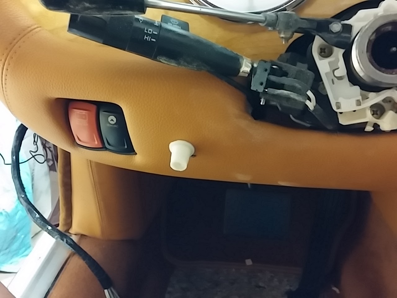
| Hazard switch wire with steering column cover installed. |
 |
| With newly created (but unpainted) knob. |
This is where the art comes in. Using Blender (www.blender.org) I designed a knob that I thought would look good and do the job. As you can see from the pictures, I went through many iterations before I got one that looked the way I wanted it to. This is the nice thing about this rapid prototyping capability of 3D printing. Each knob only took about 20 minutes to print, so I could make quick changes, print the knob and try it. Rinse and repeat.
 |
| No, there are not monster teeth! They are many attempts at creating the knob. Progression is right to left. |
The process is to first create the part in Blender (or any other 3D tool like Sketchup or Maya). There are some things you have to think about when working in the tool. First, for blender, the Z axis needs to be up. Second, you want to make sure that none of the faces obscures a vertex. This is a bit fiddly on a very complex object, but it is critical because the slicing software cannot determine how to create a face if the vertex is hidden. Third, you need to make sure to remove any duplicate vertexes (Mesh > Vertex > Remove Doubles). Forth, you need to make sure the mesh is manifold, meaning, here are no holes. You can check this in edit mode by deselecting everything and then using the Select > Non-manifold option. This will highlight any vertices that do not have a face connecting them. Finally, you need to apply a Triangulate modifier. This modifier will convert all the polygons to triangle which helps the STL conversion. Once all the above prep is done, the file is exported as an .STL file, making sure that all modifiers are applied (Blender has an option to do this during the export).
 |
| Final knob in Blender. |
Once you have the file exported, the next step is to "slice" it. I use an open source software called Slic3r to do this. There are many other tools available and each has strengths and weaknesses. You find this out when you get into the REPRAP world. I like this tool because I know it best and get good results for what I print!
The tool has all the parameters you need to create a driver file that can be used on the printer, things like how thick each layer should be, do you need supporting material so that overhangs do not sag, how much infill you want inside the object, how hot the printer extruder should be, etc. It's pretty complicated and depends on the type of material you are printing. A lot of trial and error (and reading the internet) is needed to get the correct settings, but I think I found a sweet spot.
 |
| Slic3r Application with knob loaded and ready for export to GCODE. |
Once you bring your STL file into the slicer tool, you run the tool to create a GCODE file. The GCODE file is used by the printer driver software to drive the printer. It contains data needed to set the printer (extruder temp, print head speed, etc.) as well as data for each slice of the object. The software will look at the STL file from the bottom and determine how to drive the printer head to print that layer. It then moves up and determines the next layer. It does this until each layer for the object is defined.
Once you have the GCODE file, you are ready to print. Depending upon your printer make, there are various applications to run it. I use Pronterface, which is a common open source print driver application. Pronterface is the direct interface with the printer. It allows you to manually set the temperatures of the extruders, move the print head and print base and several other items. With the GCODE file loaded into the Pronterface application, it's a simple matter of heating everything up and then pressing the Print button.
 |
| Pronterface application used to drive the printer. The knob is loaded and the printer is ready to go. |
 |
| Printer putting down second layer of plastic. The front face of the knob is sitting against the bed. |
 |
| Knob just after print finished. |
This sounds like a lot of work, but the biggest amount of time is taken in creating the model in Blender. Slicing takes almost no time if all the prep work is done correctly in Blender and the print takes as long as it takes based on the complexity and size of the model.
Another item I created was the dimmer control knob. As I talked about in a prior post (
http://leapingv8s.blogspot.com/2016/04/dash-you-would-think-id-be-done-by-now.html), I had to find a place to put the dimmer control and decided to put it between the steering column and the master power switch. Since this is a very custom solution, I needed to create a custom knob. Using the same steps as above, I created the knob that you see here:
 |
| Dimmer control shaft sticking out of fascia. |
 |
| With knob. |
So there you have it!
The really cool thing is that I can send the GCODE file to a custom manufacturer and they can create my objects is other materials like aluminum or steel. The same file is used to drive 4 axis milling machines and other industrial tools, so if I needed something in a more durable material then ABS plastic, all I have to do is find a vendor and send them the file!