Monday, June 13, 2016

No Panel Hanging, But Lots Of Troubleshooting


Dateline – 06/11 and 06/12, 2016 – I got all but the fenders back from the paint shop this week and was planning on having a panel hanging party on Saturday, but yours truly forgot to get the stainless steel hardware needed to put everything together.  I went to the local McClendons, but they didn’t have anything with the thread pattern I needed.  They sell the nuts, but not the bolts! I didn’t have enough time to go to Tacoma Screw, which is only open during the week until 5:00pm, so the party has been delayed.

I did get a chance to continue troubleshooting the wiring in the car.  Boy was that a challenge and I ended up cutting almost all the wire wrapping to do it.  Heavy sigh! 
Saturday morning, I started looking at the heater controls which were not working at all.  I figured out that I was not getting power to the #3 fuse and had to trace that back to a bad connection.  Once I get that figured out, both the heater fans and the temperature controls worked like a champ, but that was three hours of work!

Next was the windshield washer.  Guess what.  It worked right out of the box! 
How about the wipers?  Not so lucky.  The low speed and park functions were working fine but the high speed did not work.  There was no reason for it not to since all the wiring looked correct.  So I pulled the wiper motor out, which is a real PITA, then opened the motor to find the high speed brush was stuck.  After a bit of soldering and cleaning it started working fine.

My final item of the day was to get the side markers and headlights working.  Of course, neither worked out the box.  My original goal was to install a daytime running light and auto headlight module.  I thought it would be cool to have something like that.  Well, that was the first thing I took out!  Too much complication.  After rewiring with that out the system, I tried the side makers, which worked fine.  Then the headlights, which did not work!  Troubleshot this for about two hours before I discovered a bad ground on the left headlight!  Of course, I didn’t think of trying it on the right to see if they work!  So, both headlights working, high and low beam.  That was a full Saturday and I was done.

Sunday I decided to attack some of the accessories.  I noticed the interior lights were not coming on, but after trying a different switch, they worked fine.  Next I tried the new switch I installed on the dash to turn on the lights.  Not so good.  Blew a 20 amp fuse.  After looking at how I wired it, I can see why.  Battery direct to ground!  Okay, rewired that one and now the interior lights work.
Next was to try the map lights, which are mounted on the new rear view mirror I purchased.  Worked great!

How about the radio?  It worked too!  

Now I’m feeling pretty cocky!  So, I have a few switches that are blank right now.  The radiator fan unit I bought has a manual override that can be used to turn the fans on when you turn on the A/C or if you just want to have a switch in the car to turn them on.  So, I wired in one of the unused switches to power the fan.  And the fan worked great!

My final thing was to wire in the “starter kill” switch.  After taking out the keyless start system I originally put in, I didn’t have a starter lockout and still wanted one.  I have a space in the center console for the original start switch which was going to be a momentary on type since it was going to be used to turn over the engine.  I bought a new switch that is on/off and wired that in with a relay.  So now, without that button pressed, the starter will not engage.

Now, everything appears to be working except for the center indicator cluster which I need to etch a new circuit board for so it was time to put all the wiring back together.  I spent four hours trying to re-bundle the wires and the more I worked on it, the more I disliked how it was coming together.  I’ve always been worried about the relay position inside the center console.  If any of these relays goes bad, I have to take the entire thing apart to get to them.  Plus, there is a lot of wire going in a very tight space.  I’m just thinking this is going to be a place for failure. 

So I’m going to rewire it again.  I know!  I’ve rewired this three times now.  But I just don’t feel comfortable with it and I don’t want to have a breakdown on the freeway because of my wiring.  I’ve spent too much time working on this car to leave something in which I not at all comfortable.   So, time to get out the wire crimpers and do this again. 

Looking at the complexity I took out of the system over the weekend, I’m really thinking I can make it even simpler by removing a lot of the relays.  I think I’ve been over protective of my switches by using so many relays.  Also, I think I can move the relays up under the dash pad instead of having them inside the center console.  This will make them easier to get to if I need to troubleshot and will remove a great deal of the wiring out of the center console. 

Can I ever leave well enough alone?  Probably not.

Monday, June 6, 2016

Getting the Kinks Out

Dateline - 06/04/2016 - This weekend was dedicated to getting some of the electrical kinks out.  First I noticed the speedometer was not working.  After some troubleshooting I found that it was not getting hot from ignition.  Probably something I modified cut the power to the gauge, so I ran a hot from the tach and now it works, or at least, it is zeroing out and it shows 2 miles on the odometer!

Next I was worried that the electric fans were not coming on for engine cooling.  I did some initial troubleshooting then decided to check the instructions to see if they were supposed to come on.  Sure enough, RTFM!  The fans come on at about 160 degrees.  I never ran the engine long enough get it that hot, so of course the fans didn't come on  I do need to test that before we put the hood back on because it will be a real pain to work on after that if there is a problem.

Now it was time to wire in the new battery cutoff switch that I got from Amazon during the week.  I took out the solenoid that I had in place first, then I needed to make some brackets for the switch, which is designed to mount into a dash or bulkhead.  After making the brackets, sand blasting, tin plating and polishing them, I installed them in the same place as the solenoid.  I did not have the hardware to mount the switch on the brackets, so I used a couple of zip ties to hold it in place.

Next started troubleshooting a light that was coming on in my new "info center".  It was the oil pressure light and it stayed on all the time.  After doing some review, I realized that I have it wired backward.  For the oil pressure light, I need hot going through the bulb to the sender which goes to ground.  I have it wired so that the hot comes from the sender through the bulb to ground.  So, the hot being send to the sender from the gauge is going through the bulb to ground, keeping it lit.  I need to reverse that.  This means I need to etch a new circuit board!  Oh well.  A new board will allow me to be able to make a few changes that I wanted to do anyway (e.g. put a low brake fluid warning and hazard light indicator) and put tabs on the board that I can use to secure it via screws to the back of the dash board.

Next I tried the hazard and turn signals which were not working.  But it was getting hot in the garage (we broke temperature records this weekend) and decided to call it a day of actually working in the garage, but did spend time on the computer redrawing the circuit board so that I can etch a new one.

Dateline - 06/05/2016 - Sunday was going to be a day to figure out why the blinkers and hazard doesn't work as well as try the climate control.  First I needed to deal with a few things under the hood.  There were two ground wires, one from the speedo sending unit and one from the block to the body that needed to be attached.  I took care of that.

Next I installed the climate control box, but it did not work at all.  No fans, no temperature control.  I was going to dive into that, but decided to work on the blinkers instead.

Wow!  The blinkers.  What PITA.  Of course, I was making it more complicated then it needed to be by trying to use the hazard switch that was part of the GM blinker switch.  I must of spent three hours just trying to remember what I did three years ago and re-figuring out how the car was originally wired.  I know this worked when I first wired it, but it sure wasn't working now.  So, I decided to go back to the way the car was originally wired, with a separate hazard switch.  Now that the battery cutoff switch is no longer being used, I decided to use that as my hazard switch.  So after four hours of troubleshooting and rewiring, I now have hazard and blinkers that work.  What this means is that all that work I did to create that switch with my 3D printer was for nought!  "Best laid plans" I guess.

By the time I stopped working on the car is was 90 degrees outside and I needed to stop.  I plan to spend some time this week after work to get the climate controls working and test out the rest of the electrical work.  I'm hoping to have the rest of the body panels back this week and I'm planning to have a panel hanging party on Saturday so I really would like to have all the electrical work done before then!

Tuesday, May 31, 2016

Big Victory and a Small Defeat


Dateline – 05/30/2016 – As you can see from this post’s title, I made some major headway this weekend, but also had a bit of an issue.  I’ll cover these in sequence.  First, I got the rubber gaskets from Amazon for the fuel caps and they worked perfectly!  Here are pictures of the right hand filler cap installed!  Nice to have something go easily.
Right gas cap closed
Right gas cap open.  Note rubber seal.
Next, I started working on the power.  I bought a new battery several weeks ago, but had not actually tried it.  So, first I went through and made sure that all the exposed electrical was taped over so that I wouldn’t short anything out.  Next I put in fuses and hooked up the battery.  NOTHING!  Grrr!  So I started troubleshooting.  I have a master power switch in the car that goes to a 200 amp relay in the engine compartment.  I looked it over and thought that I had connected it incorrectly.  I swapped a wire turned it on and POOF!  Smoke everywhere!!!!!  It’s amazing what happens when you put 600 amps through a 16 gauge wire!  Yup.  Fried and melted!  Literally melted the copper wire in half that went to ground and melted the wire running from the coil to the switch along its entire length.  I had to cut apart all my nice wire wrapping to pull the wire out.  Fortunately, it melted to surrounding wire, but did not damage any of it.  But I think my car is going to smell like burnt electrics for a long time!

So, after that I took the solenoid out of the loop (going to put a manual power cutoff there because I realize now that a solenoid is still going to draw the battery down) and hooked the power back up.  No "poofs" this time.

Now I decided to see if I could get power.  Some time ago I decided to go with a power on and starter button instead of using the ignition switch.  Well that does not appear to be working because I could get no power.  Grrrr!  So, I took that out of the loop and now I think I’m going to keep it out.  I was never comfortable with the main power being driven through a set of relays.  I could just see that being a major failure.  So I’m going to go back to the old system.  KISS.  I don’t know what I’m going to use the two push button switches for now, but I’ll figure something out.

So with the old ignition switch installed, I got power and was able to turn the engine over!  Yah!
After frying electrical, I decided to see if I could get the engine started.  First, I wanted to make sure the distributor was close to the correct timing and that I had the firing order correct.  I had swapped the distributor cap and I wanted to be sure, so pulled the cap and did a check.  All was good.

Now I needed to line the distributor to TDC.  I needed to turn the engine over easily, so I pulled the plugs and brought engine to TDC.  Looking at the distributor, I noticed it was 180 degrees out.  Hmmm.  Okay, easy to fix and while I have the distributor out, I can prime the engine oil by manually running the oil pump.  So I pulled the distributor and with a very long screwdriver, drove the oil pump until it got a lot of turning resistance.  Then I put the distributor back in at the correct angle, at least I thought it was. 

Next I put the plugs back in, installed the distributor cap, plugged in the wires and then poured some gas down the carb.

Now the time of reckoning.  Will it start?  It turned over and BLOOM backfire through the carb.  Every time I’ve seen that, it is the timing being off by 180 degrees.  Damned!  I had it right to begin with.  So once again I pulled the plugs, only this time I also pulled off the valve cover on the odd (driver side) bank of cylinders and watched the rocker arms to get into the power stroke, not the intake stroke!  Do’h.  That was stupid!

So, plugs back in, wires connected, gas in the carb and VROOM!  Engine starts and runs for a second.  YA!

I do that a few more times, then decide to put gas in the tank for the first time.  I put about a gallon in the right hand tank, and knowing that I’ve no fuel anywhere in the lines or filters, I took the top off the carb and filled up the bowls so that the engine would run long enough to prime.  I started the engine and sure enough, it kept running!  And I had good oil pressure and the volt meter was showing a good 14 volt charge!  I let the engine run until it heated up enough to start flowing water out the radiator filler, which was uncapped, but that was enough to get it hot and to fill the garage full of fumes from the exhaust manifolds and exhaust pipes.  Here is a video of the engine running along with gauges showing oil pressure and amps


So what is left.  Well I still have some troubleshooting to do.  The clock is not working.  I need to put enough gas in to see if the gas gauge is working.  I need to heat the engine up to find out if the temperature gauge is working.  I also didn’t check the tach to see if that was working correctly.  And I’m not sure if the electric radiator fan came on or not.  I believe it should be on low at all times and speed up after a certain temp.  Also, I need to check to see if the left/right fuel switch is working correctly.  I did check that the solenoids are working, but I don’t know if the gauge is working or not.  And I have to rewire the ignition to use the switch again, pull out the relays and wiring.

So, the day started off kinda of crappy, but ended on a very high note.

Tuesday, May 24, 2016

Fuel Delivery System

Dateline - 05/21/2016 - Worked on the fuel delivery system this weekend.  The first thing was to get the gas caps installed.  These are a Jaguar work of mechanical complexity.  Talk about over engineered!  They consist of a base filler neck that slides into the tank with an o-ring and screws into the body with four machine screws.  There is a vapor recovery port that needs to have a fuel line connected to it (part of the fuel recovery system I installed earlier (http://leapingv8s.blogspot.com/2016/01/started-on-trunk.html).  There is also the chrome cap which has mounted on it:

  • A lock
  • The lock cover
  • The latch/spring mechanism
  • The Fuel opening seal mechanism

The fuel opening seal mechanism is complex in its own right.  It consists of:

  • A spring loaded plate that mounts to the chrome cap
  • A cup shaped plug that holds the seal for the tank and fits into the filler hole
  • A spring loaded plug that has a rubber seal on it which fits into the cup.  This is used to allow excess pressure to escape the tank.
  • Yet another spring loaded plug in the center of the bigger plug that allows any water that gets into the cup to drain into the tank.

Exploded view of gas cap
YIKES!  Three separate spring loaded components, two rubber seals and a cup that can potentially fill up with water!  All to cover the filler of the gas tank.

So, needless to say, all of these metal parts become very corroded over time, especially the inside of the cup and the components inside.  It took four complete filler caps (the two on the car and two that I purchased on-line) to build up the two I needed.  All of the corroded parts got a good sandblasting and tin plating to help avoid corrosion in the future.

The problematic piece is the rubber seal used on the tank filler.  You can't get this anywhere.  I did some amazon.com spelunking and I think I found a rubber replacement.  I was hoping they would be in this weekend, but they didn't come in.  They came in last night (Monday) and they fit beautifully!  A little larger in outside diameter, but I can cut it back if needed.

The other part of the fuel delivery that I worked on was the steel tubing running under the car to the engine.  I recorded earlier about the steel fuel line from the tanks being crushed  (http://leapingv8s.blogspot.com/2015/10/the-jag-is-home.html).  The crushed piece was were the fuel line ran along the side of the frame rail.  I had cut the offending piece off and was going to just go with the shorter fuel line and a longer rubber line running to the pump.  But with everything installed, I didn't like how close the rubber fuel line would to the exhaust pipe.  So I decided to go ahead and make a new steel hard line that would run along the frame rail to the front, ending closer to the fuel pump.  I got out my trusty pipe bending tools and genned up a piece that fit closely to the frame rail to a good point under the car.  I then cut the existing tubing to fit and used a brass union compression fitting to put the two pieces together.  This left me with a lot cleaner installation, and just a short piece of rubber hose from the hard line to the fuel pump.  Plus, I got a chance to play with my tubing bending tools!

New fuel line and rubber hose leading to fuel pump
My only concern is the proximity of the line to the exhaust manifold and collectors.  I'm going to monitor this to make sure I'm not getting fuel vaporization.  If I do, I'll probably need to get some heat shielding.  It is something to be watchful of.

So this completes the fuel delivery.  I should be ready to put gas in the tanks!  For all intents and purposes, except for a small amount of wiring, the engine should be ready to start!  I need to wire in the ignition and starter buttons, put in fuses and hook up the battery.  I've gone around the car and put electrical tape over all the disconnected wires, so it should be pretty safe.  Maybe next weekend?

Also, I talked to the paint shop and they are thinking the panels will be done this week!  Going to need to plan that panel hanging party!

Monday, May 16, 2016

Not a Lot of Progress

Dateline - 05/14/2016.  Didn't make a lot of headway this weekend.  Spent most of the day trying to get the B&M shifter to work correctly.  This required crawling under the car, then getting up and moving the shifter, then crawling under the car again, repeat, repeat, repeat, repeat repeat!  Yikes!

For the life of me I could not get the shifter to engage correctly.  The idea is that it needs to engage correctly at the end of the range (e.g. Park and 1st) with no binding on the linkage.  I could not get it to do that.  I could get park to work and 1st would be bound.  Get 1st to work and Park would be bound.  Three hours of under the car, in the cabin, under the car, in the cabin really took a toll.  Finally, I stopped and looked at the installation of the cable on the shifter mechanism.  Low and behold, I installed the cable on the shifter incorrectly! All I can say is, "RTFM Ed!"  After reinstalling the cable correctly, everything worked perfectly!  That was a real waste of four hours and a lot of crawling under the car!

To get a little break, I decided to work on the gas caps.  I partially installed the right hand gas cap base, but didn't have the correct hardware, so it is in there with a couple of screws.  I also bought two complete gas caps from ebay because I needed some parts that had broken on the originals.  Both of these are in pretty rough shape but these things are unobtainium so you have to take what you can get.  I spend about an hour sandblasting the parts, but now need to find some fuel proof rubber material for the gaskets.  Looks like I need to spend some hours on the interwebs!

I do have good news on the rest of the body panels. I called the paint shop and they said they should have the rest of the panels ready to pick up by the end of the week!  I'm getting close to being done with the interior so this will be good timing.  I'll store the parts in the house until I'm ready to hang them, but that shouldn't be to long!

Thursday, May 12, 2016

Art to Part

Dateline - 05/07/2016 - This weekend I spend doing more mechanical work under the car.  I had a few things hanging, literally under the car that needed to be taken care of.  First was wiring to the electronic speedometer sensor on the transmission.  Another was the Transmission lockout that is connected to the brake light switch.  Basic wiring stuff, but it takes time to create a nice wire loom and fit connectors.

Still another thing that I needed to do was hook up the B&M shifter cable to the transmission.  I had jury rigged this before (http://leapingv8s.blogspot.com/2009/06/steering-wheel-shifter-and-tunes-plus.html) and after I looked at it again, I really wasn't happy with the results since it didn't look like it was completely engaging in Park.  So this time I decided to install this the correct way, but need to get a special bracket from B&M for my TH700R4 transmission.  So I put that on order and am waiting for the parts.

I also started getting ready to start the car by changing the oil and filter, filling the antifreeze and power steering pump.  I even filled the window washer reservoir and bought a new battery.  All I need now is fuel. I still have to put the fuel line from the gas tanks to the engine bay back up.  I took it  down to deal with the crimped fuel line last winter and still need to put it back.  I also need to put the fuel tank caps back on.  I needed to paint the area around the fillers (I don't know why the paint shop didn't paint them but they didn't), so I used high temp engine paint (black) to finish that off.  Now I just need to reinstall the caps.

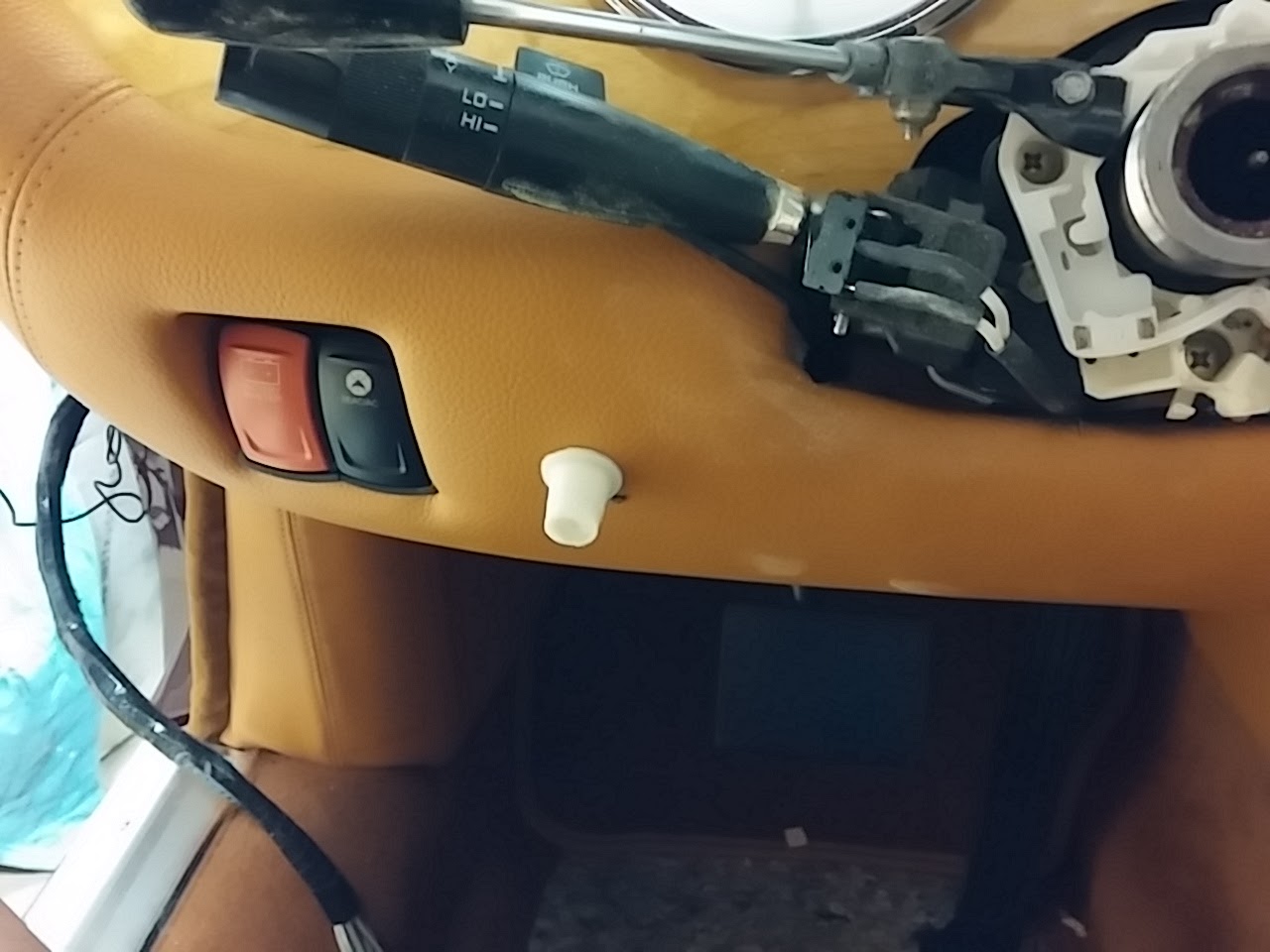
So, you may be wondering about the name of my post this week.  During the week I did some more part creation on my 3D printer.  After putting all the dash back together, I realized I needed a knob for the hazard light switch.  If you remember, I use a mid-70's GM indicator switch assembly to replace the non-functional Jaguar item.  What I liked about that solution is that it has the hazard switch is built into mechanism. This means that I don't have to wire in a different switch.  But because of the way I installed the turn indicator, the hazard switch is at the 4:00 o'clock position, which puts it a bit out of the way.  I had to glue a piece of brass wire in place to extend the mechanism outside of the steering column cover and once I got everything into place, I realized I needed a knob.

Steering column with indicator switch mechanism exposed.  Note brass wire at the 4:00 position.  This is connected to the hazard switch.

Hazard switch wire with steering column cover installed.

With newly created (but unpainted) knob.


This is where the art comes in.  Using Blender (www.blender.org) I designed a knob that I thought would look good and do the job.  As you can see from the pictures, I went through many iterations before I got one that looked the way I wanted it to.  This is the nice thing about this rapid prototyping capability of 3D printing.  Each knob only took about 20 minutes to print, so I could make quick changes, print the knob and try it.  Rinse and repeat.

No, there are not monster teeth! They are many attempts at creating the knob.  Progression is right to left.
The process is to first create the part in Blender (or any other 3D tool like Sketchup or Maya).  There are some things you have to think about when working in the tool.  First, for blender, the Z axis needs to be up.  Second, you want to make sure that none of the faces obscures a vertex.  This is a bit fiddly on a very complex object, but it is critical because the slicing software cannot determine how to create a face if the vertex is hidden.  Third, you need to make sure to remove any duplicate vertexes (Mesh > Vertex > Remove Doubles).  Forth, you need to make sure the mesh is manifold, meaning, here are no holes.  You can check this in edit mode by deselecting everything and then using the Select > Non-manifold option.  This will highlight any vertices that do not have a face connecting them.  Finally, you need to apply a Triangulate modifier.  This modifier will convert all the polygons to triangle which helps the STL conversion.  Once all the above prep is done, the file is exported as an .STL file, making sure that all modifiers are applied (Blender has an option to do this during the export).

Final knob in Blender.
Once you have the file exported, the next step is to "slice" it.  I use an open source software called Slic3r to do this.  There are many other tools available and each has strengths and weaknesses.  You find this out when you get into the REPRAP world.  I like this tool because I know it best and get good results for what I print!

The tool has all the parameters you need to create a driver file that can be used on the printer, things like how thick each layer should be, do you need supporting material so that overhangs do not sag, how much infill you want inside the object, how hot the printer extruder should be, etc.  It's pretty complicated and depends on the type of material you are printing.  A lot of trial and error (and reading the internet) is needed to get the correct settings, but I think I found a sweet spot.

Slic3r Application with knob loaded and ready for export to GCODE.
Once you bring your STL file into the slicer tool, you run the tool to create a GCODE file.  The GCODE file is used by the printer driver software to drive the printer.  It contains data needed to set the printer (extruder temp, print head speed, etc.) as well as data for each slice of the object.  The software will look at the STL file from the bottom and determine how to drive the printer head to print that layer.  It then moves up and determines the next layer.  It does this until each layer for the object is defined.

Once you have the GCODE file, you are ready to print.  Depending upon your printer make, there are various applications to run it.  I use Pronterface, which is a common open source print driver application.  Pronterface is the direct interface with the printer.  It allows you to manually set the temperatures of the extruders, move the print head and print base and several other items.  With the GCODE file loaded into the Pronterface application, it's a simple matter of heating everything up and then pressing the Print button. 
Pronterface application used to drive the printer.  The knob is loaded and the printer is ready to go.
Printer putting down second layer of plastic.  The front face of the knob is sitting against the bed.
Knob just after print finished.
This sounds like a lot of work, but the biggest amount of time is taken in creating the model in Blender.  Slicing takes almost no time if all the prep work is done correctly in Blender and the print takes as long as it takes based on the complexity and size of the model.

Another item I created was the dimmer control knob.  As I talked about in a prior post (http://leapingv8s.blogspot.com/2016/04/dash-you-would-think-id-be-done-by-now.html), I had to find a place to put the dimmer control and decided to put it between the steering column and the master power switch.  Since this is a very custom solution, I needed to create a custom knob.  Using the same steps as above, I created the knob that you see here:
Dimmer control shaft sticking out of fascia.
With knob.

So there you have it!

The really cool thing is that I can send the GCODE file to a custom manufacturer and they can create my objects is other materials like aluminum or steel.  The same file is used to drive 4 axis milling machines and other industrial tools, so if I needed something in a more durable material then ABS plastic, all I have to do is find a vendor and send them the file!

Monday, May 2, 2016

Machinical Work

Dateline - 04/30/2016 - I was getting a bit tired of working on the interior so I decided to do some mechanical work this weekend.  My main focus was getting the exhaust manifolds sandblasted, coated and installed.  This took a lot of time because I could only sandblast for about 10 minutes before I ran out of air and needed to stop to let the air compressor build back up.  I don't like to continue sandblasting while the air compressor is running because it takes that much more time to build up pressure and causes the compressor to get really hot.  So, I can do about  4" x 4" section, then stop and do something else on the car.

The something else was to put on new rubber brake lines to the front wheels and hook up the brake lines to the master cylinder.  I had purchased brake lines several years ago and have been putting off putting them on until I got close to done.  This seemed like a good time, so I installed both sides.  I also installed the brake pipes to the master cylinder, which wasn't difficult.

I also took the plugs out of the engine, put some oil into the cylinders and turned the engine by hand to make sure the pistons are free.  Everything turned easily, so that was a good sign. 

So, once I got the exhaust manifolds sandblasted, I treated each one with Calyx manifold coating (http://www.eastwood.com/calyx-manifold-coating.html).  This paste is very easy to put on with a toothbrush and really makes the manifolds look good. 

Once coated, I installed the manifolds on the engine and connected the exhaust collectors.  The passenger side is pretty easy, but the driver side was a real bear because of the steering rack.  Needed to have multiple extensions and universal joints to get the inside bolt tight.  But patience prevailed and I got everything installed.  Here are pictures:

Before and after sandblasting
Exhausts.  Top pre-sandblasting, bottom, sandblasted and treated with Calyx
Passenger side with exhaust and plug wires
Driver side exhaust with plug wires
So, I don't have much left to do in the engine bay at this point.  Need to put in fluids (antifreeze, power steering, brakes and change the engine oil/filter), and connect the fuel line from the gas tanks that I disconnected.